



Contents: Engine 1.2 l ⬇ Engine 1.4 l ⬇ Petrol engines 1.8 l ⬇ Diesel engines 2.0 l (CFHC, CFJA and…⬇
Engine 1.2 l
1. The intercooler installation details are shown in the illustration. The radiator for the intercooler is combined with the radiator of the engine cooling system; description of radiator removal/installation is given in Chapter 3.
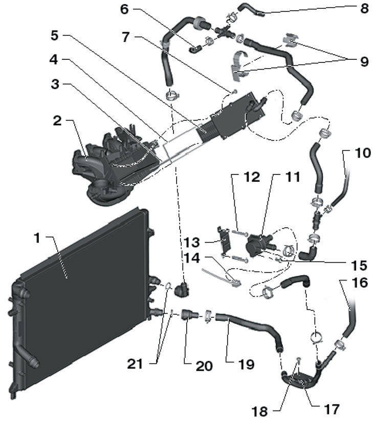
6.1. Details of installation of intercooler of 1.2 l engine. 1. Engine cooling system radiator, combined with intercooler radiator; 2. Inlet manifold; 3. Compaction; 4. Gasket; 5. Intercooler; 6, 10. Coolant hose, to turbocharger; 7. Bolts are tightened by hand, then with a force of 7 Nm; 8. Coolant hose, to the expansion tank; 9. Coolant hose holders; 11. Coolant circulation pump "V50"; 12, 18. Bolt, 8 Nm; 13. Support; 15. Bolt, 10 Nm; 16. Coolant hose, to oil cooler; 17. Coolant pipe, attached to the oil pan; 18. Lower coolant hose; 20. Connection; 21. Sealing ring.
2. Disconnect the connector (1 in the illustration) and disconnect the hose (3) going from the Evaporative Canister Purge Valve No. 1 "N80". Disconnect the lines with the non-return valve (5) and the solenoid valve "N80" from the intake manifold. Disconnect the coolant hoses (3) from the intercooler, unscrew the ignition module mounting bolts and carefully place it on the cylinder head cover. Remove the intercooler bolts (4) and carefully pull it out of the intake manifold. Drain the remaining coolant from the intercooler.
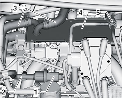
6.2. Removing the intercooler.
3. Push the seal on (1 in the illustration) on the edge of the intercooler (2) in the direction of the arrow, make sure that the new gasket is correctly seated on the intake manifold and push the intercooler into the intake manifold until it stops, without allowing it to become skewed.
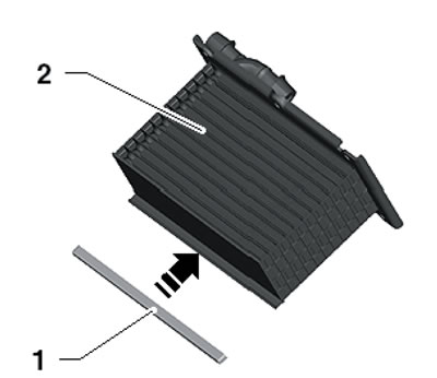
6.3. Installing the seal.
4. Tighten all intercooler mounting bolts in a diagonal order by hand, and then tighten them in the same order to 7 Nm.
Engine 1.4 l
5. The intercooler installation details are shown in the illustration. Proceed in the same way as for the 1.2L engine (see above).
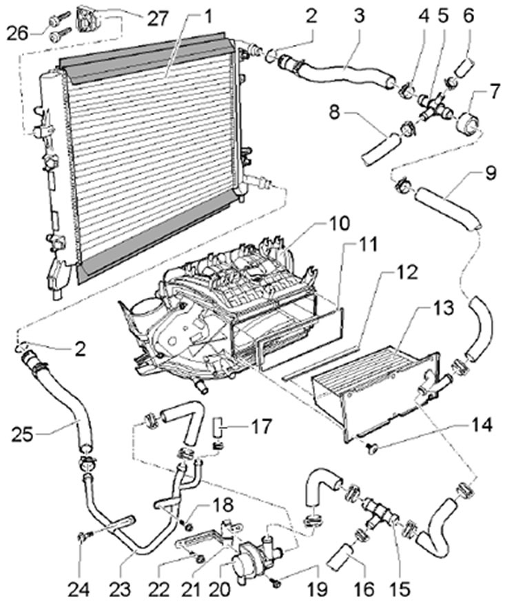
6.5. Intercooler installation details (1.4L engine). 1. Additional radiator for intercooler, with upper and lower sealing strips; 2. Sealing ring; 3. Upper coolant hose; 4. Spring band clamp; 5. Connecting tube; 6. Coolant hose, to the expansion tank; 7. Protective sleeve; 8. Coolant hose, to turbocharger; 9, 16, 17. Coolant hose; 10. Inlet manifold; 11. Gasket; 12. Sealing strip; 13. Intercooler; 14. Bolt, 7 Nm; 15. Connecting tube; 18, 19, 24. Bolt, 10 Nm; 20. Coolant circulation pump "V50"; 21. Bracket; 22. Bolt, 20 Nm; 23. Coolant pipe; 25. Lower coolant hose.
Petrol engines 1.8 l
6. Intercooler installation details are shown in the illustration.
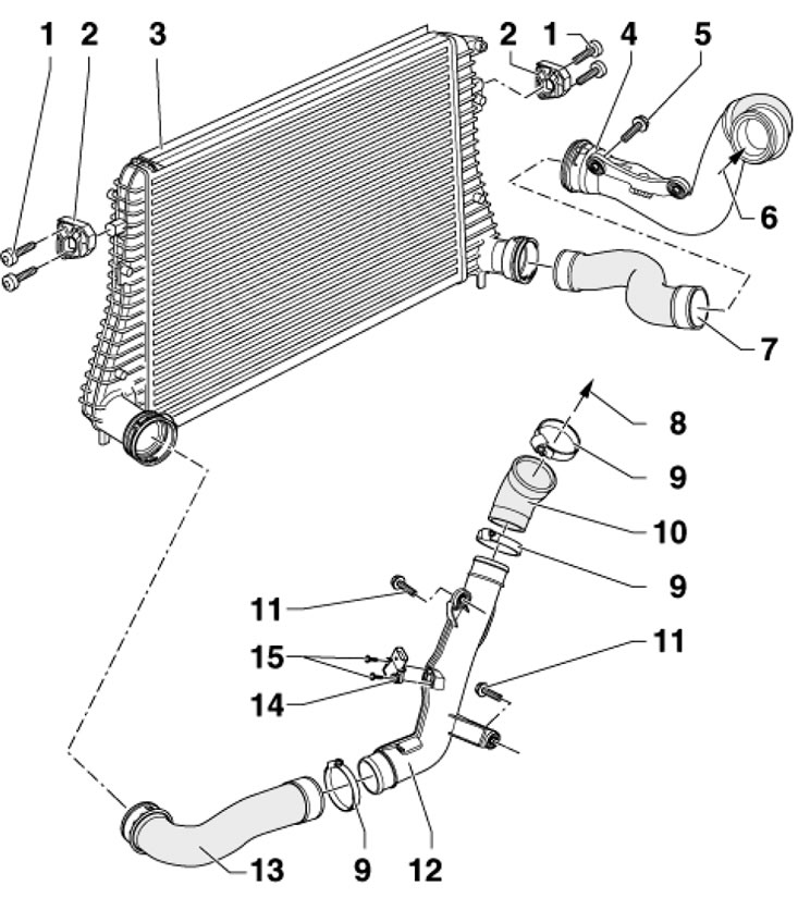
6.6. Intercooler installation details (petrol engines 1.8). 1. Bolt, 7 Nm; 2. Intercooler support; 3. Intercooler; 4, 12. Boost air pipe; 5, 11. Bolt, 8 Nm; 6. From a turbocharger; 7, 10, 13. Charge air hose; 8. To the throttle module; 9. Clamp; 14. Boost pressure sensor "G31"; 15. Bolt, 5 Nm.
7. Remove the engine cooling system radiator (see Chapter 3).
8. Remove the front bumper (see Chapter 11).
9. Disconnect the left and right pressure air hoses from the intercooler.
10. Remove the bolts (see illustration) refrigeration unit condenser fastenings. Do not disconnect, kink or pull refrigerant lines.
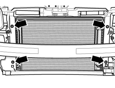
6.10. Fastening the capacitor.
12. Remove the bolts (1 in illustration 6.6) intercooler mounts on both sides.
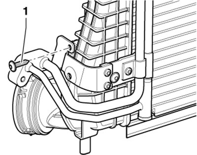
6.12. Refrigerant line mounting bolt.
13. With the help of an assistant, push the intercooler away from the hood latch holder to provide access to the bolt (1 in the illustration) refrigerant line fastenings. Unscrew this bolt and carefully remove the intercooler downwards.
14. Installation is carried out in reverse order. Use new O-rings.
Diesel engines 2.0 l (CFHC, CFJA and CLCB)
15. Intercooler installation details are shown in the illustration.
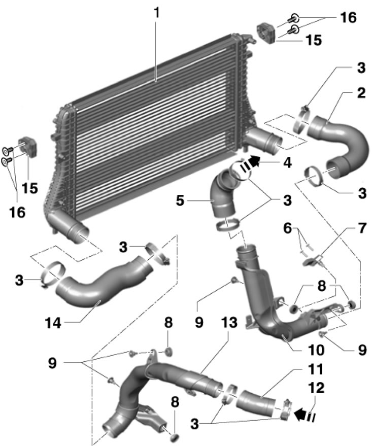
6.15. Intercooler installation details (2.0L CFHC, CFJA and CLCB engines). 1. Intercooler; 2. Right boost air hose; 3. Threaded clamp; 4. To the throttle module; 5. Connecting hose, cold side, lower; 6, 16. Bolts, 5 Nm; 7. Boost pressure sensor "G31" with IAT sensor "G42"; 8. Rubber gasket; 9. Bolt, 10 Nm; 10. Right boost air pipe; 11. Connecting hose; 12. From a turbocharger; 13. Left boost air pipe; 14. Left boost air hose; 15. Support.