



Contents: Relieving fuel pressure in the…⬇ Relieving fuel pressure in the…⬇ Bleeding (bleeding) the fuel supply…⬇ Pumping fuel out of the tank (petrol…⬇
Relieving fuel pressure in the low-pressure circuit of gasoline models
Please note: The pressure in the low-pressure circuit of FSI models can reach 6 bar!
1. Remove the fuel pump or fuel pump control unit fuse from the relay and fuse box (see Chapter 12).
2. Start the engine and let it run until all the gasoline remaining in the fuel lines is used up (until the engine stalls).
3. Crank the engine with the starter for approximately 5 seconds to ensure that the pressure in the fuel rail has been completely released.
4. Install the fuel pump fuse.
5. Even after releasing the fuel pressure, when disconnecting the fuel lines, wrap the connection with a cloth and slowly loosen the connection, allowing the fuel to soak into the cloth.
Relieving fuel pressure in the high-pressure circuit of gasoline models
Caution: The pressure in the high-pressure circuit can reach 120 bar (on 1.2 and 1.4 l models) or 150 bar (on 1.8 l models)!
6. On 1.8 l engines, disconnect the connector of the fuel pressure regulation valve "N247" (see Section 10), then start the engine and let it idle for about 10 seconds. This will reduce the pressure to about 6 bar.
7. On 1.2 and 1.4 l engines, connect the VAS5051 diagnostic tool (see Chapter 5), perform its function "Remove high fuel pressure" ("High Fuel Pressure Relief"), then turn the ignition off. In this way the pressure is reduced to approximately 6 bar.
8. Wrap the high pressure circuit connection with a cloth and slowly loosen the connection, allowing the fuel to soak into the cloth.
9. After finishing the work, read the ECM fault codes and clear them (see Chapter 5).
Bleeding (bleeding) the fuel supply system of diesel models
10. Bleeding the fuel supply system is necessary after removing the parts located between the fuel tank and the high-pressure fuel pump. The purpose of bleeding is to prevent the high-pressure fuel pump from running dry, which can lead to its failure, and to ensure reliable engine starting.
11. When bleeding, the DSG must be set to position "P", the fuel tank must be filled, and the fuel temperature must be at least 15°C.
12. To bleed, connect the VAS505X diagnostic device to the vehicle's diagnostic connector, turn on the ignition, and select in self-diagnostics "Engine electronics→006 - Basic settings→Test of fuel pump for predelivery", and then press "Start" in sequence. The fuel pump will work for about a minute. Repeat this procedure three times.
13. Start the engine, let it idle for a few minutes and turn it off. Make sure there are no fuel leaks.
14. Clear fault codes and road test (see Section 20 Chapter 1), in which you accelerate at least once with the gas pedal fully depressed. If air remains in the fuel system, the engine may switch to limp mode during a road test. In this case, you should clear the fault codes and repeat the road test.
15. After the road test, check again for fuel leaks and clear the fault codes again.
Pumping fuel out of the tank (petrol models)
Note: If the fuel pump is faulty, the fuel can be pumped out using a suitable device, such as the VAS5190.
16. Turn off the ignition and electrical appliances, remove the key from the ignition switch.
17. Fold back the rear seats and their backs, remove the floor covering underneath them.
18. Unhook the lid (4 in the illustration) with the fuel pump control unit "J538" (1). On models with additional heating, additionally disconnect the 2-pin connector of the metering pump "V54", and if you plan to remove the fuel tank, remove the rubber seal from the cover and pull out the wiring.
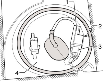
3.18. Cover with fuel pump control unit
19. Disconnect the 5-pin connector (1 in the illustration) and disconnect the black supply line (2) by pressing on its retaining ring.
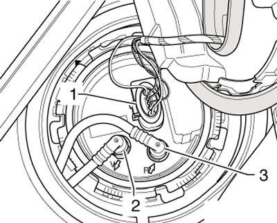
3.19. Fuel Delivery Module Connector
20. Connect adapters VAG1318/16 and VAG1318/17 to the fuel delivery module and lower the end of this "drain hose" into a fuel collection container (see illustration). Apply voltage to the fuel pump by connecting the positive wire to its contact No. 1 (1) and the negative wire to contact No. 5 (5).
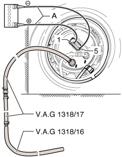
3.20. Fuel pumping