



Contents: Engine 1.2 l ⬇ Engines 1.4 l ⬇ Petrol engines 1.8 l ⬇ Diesel engines 2.0 l (CFHC, CFJA and…⬇
Caution: After disconnecting the fuel lines, plug the exposed holes to prevent dirt from entering the fuel supply system.
Engine 1.2 l
Note: When removing/installing the fuel injection pump, grasp only its body. If the piston spring set becomes loose, the tightness of the fuel injection pump will be compromised and it will need to be replaced.
1. The fuel injection pump installation details are shown in the illustration.
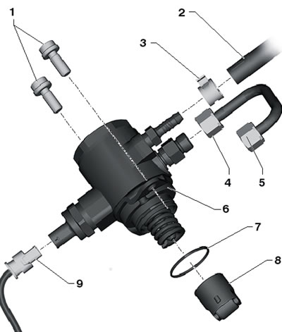
10.1. Installation details of the fuel injection pump for a 1.2 l engine 1. Bolts, 15 Nm; 2. Low pressure fuel hose, with clamp 3; 3. Spring band clamp; 4, 5. Union nuts, 25 Nm; 6. High-pressure fuel pump with valve "N276" for fuel pressure regulation; 7. O-ring, subject to replacement, lubricate with engine oil before installation; 8. Roller tappet, lubricate with engine oil before installation; 9. Electrical wiring connector
2. Turn off the ignition and electrical appliances, remove the key from the ignition switch.
3. Disconnect the connector (1 in the illustration) and disconnect the fuel supply line (2) from the high-pressure fuel pump, collecting the leaking fuel. Loosen the union nuts (3) on the pressure pipe.
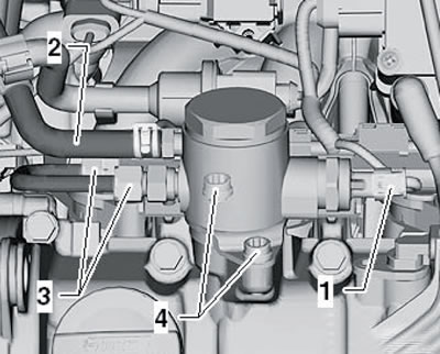
10.3. Fuel injection pump connections
Unscrew the bolt (4) evenly and remove the high-pressure fuel pump together with the roller tappet from the cylinder head cover. In this case, pull only by the fuel injection pump body.
4. Lubricate the new injection pump sealing ring and injection pump roller tappet with clean engine oil.
5. Slide the roller follower (1 in the illustration) into the cylinder head cover, install a new lubricated sealing ring (2) into the fuel injection pump groove (3) and install the fuel injection pump onto the cylinder head cover. Tighten the fuel injection pump mounting bolts by hand until they touch the flange, and then tighten them evenly with a force of 20 Nm.
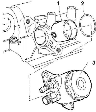
10.5. Installing the fuel injection pump
6. Using a spanner wrench, hold the threaded connection on the high-pressure fuel pump and on the fuel distribution line and tighten the union nuts of the high-pressure fuel pipe to 25 Nm. Connect the fuel injection pump wiring connector and connect the fuel supply line.
Engines 1.4 l
7. The fuel injection pump installation details are shown in the illustration. Removal and installation of the fuel injection pump are carried out in the same way as for the 1.2 l engine (see above).
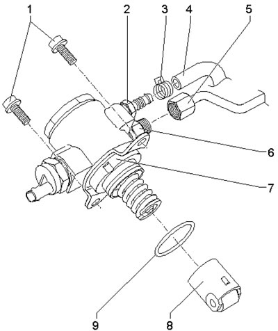
10.7. Installation details of the fuel injection pump for a 1.4 l engine 1. Bolts, 15 Nm; 2. Hose nipple 4; 3. Spring band clamp; 4. Low pressure fuel hose, with clamp 3; 5. Union nut, 25 Nm; 6. Connection, subject to replacement, 30 Nm; 7. High-pressure fuel pump with valve "N276" for fuel pressure regulation; 8. Roller tappet, lubricate with engine oil before installation; 9. O-ring, subject to replacement, lubricate with engine oil before installation
Petrol engines 1.8 l
8. The installation details of the high-pressure fuel pump and other parts involved in its operation are shown in the illustration.
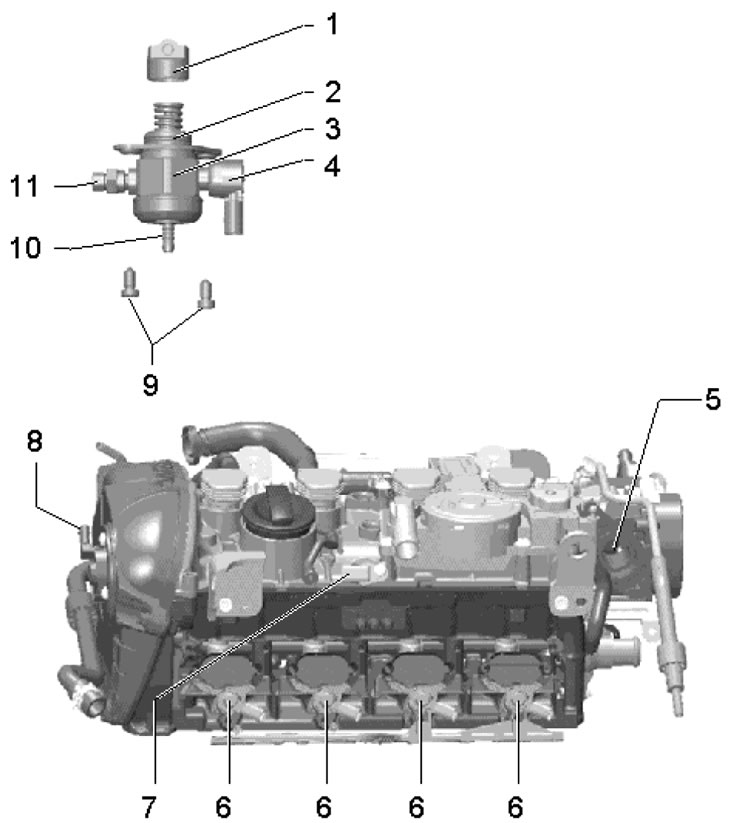
10.8. Fuel injection pump installation details (1.8 l models) 1. Roller pusher; 2. Sealing ring, subject to replacement; 3. Fuel injection pump with valve 4, the high pressure pipe is attached to the fuel injection pump with a force of 17 Nm; 4. Valve "N276" fuel pressure regulation; 5. Place in the vacuum pump for installing the high-pressure fuel pump; 6. Injectors; 7. CMP sensor "G40"; 8. Valve No. 1 "N205" for adjusting the camshaft phases; 9. Fuel injection pump bolts, subject to replacement, 10 Nm; 10. Fuel tank hose nipple; 11. Pressure tube connection, subject to replacement, 22 Nm
9. Relieve the fuel pressure (see Section 3).
10. Turn the crankshaft so that the mark on its pulley coincides with the "TDC" mark on the timing belt cover (see illustration 25.5 Chapter 2).
11. Disconnect the connector (2 in the illustration) sensor "N276" fuel pressure regulation.
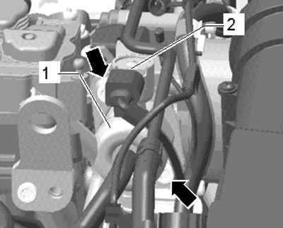
10.11. Fuel injection pump connections and fasteners
12. Disconnect the feed hose from the high-pressure fuel pump (the upper arrow in Illustration 7.21) and pressure fuel line (bottom arrow).
13. Remove the bolts (arrows in illustration 10.11) and carefully pull out the fuel injection pump. In some cases, the fuel injection pump pusher may remain in the cylinder head, in which case it should be removed separately.
14. Remove the old sealing ring from the high-pressure fuel pump, lubricate the new sealing ring with engine oil and install it on the groove of the high-pressure fuel pump.
15. Turn the crankshaft so that the plunger with the roller is at the deepest point. Insert the injection pump into the vacuum pump and tighten the injection pump bolts by hand.
16. If a used injection pump is being installed, replace its pressure line connection.
17. Tighten the fuel injection pump mounting bolts to the required torque.
18. Tighten the union nut of the fuel pressure line on the fuel distribution line, set the fuel line without tension and tighten its union nuts.
19. Connect and install the remaining parts.
Diesel engines 2.0 l (CFHC, CFJA and CLCB)
20. The details of the fuel injection pump installation are shown in the illustration.
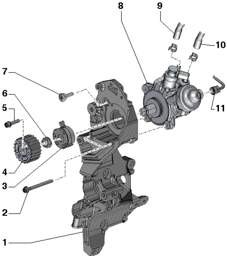
10.20. Installation details of the fuel injection pump for 2.0 l engines (CFHC, CFJA and CLCB) 1. Auxiliary units bracket; 2. Bolt, subject to replacement, 20 Nm, then tighten to an angle of 180°; 3. Hub; 4. Fuel injection pump gear; 5. Bolt, subject to replacement, 20 Nm, then tighten to an angle of 90°; 6. Nut, 95 Nm; 7. Bolt, subject to replacement, 20 Nm, then tighten to an angle of 45°; 8. Fuel injection pump with fuel metering valve "N290"; 9. Fuel supply hose; 10. Return fuel hose; 11. Fuel pressure line between the injection pump and the fuel distribution line, 15 Nm, then tighten to an angle of 60°
Caution: After removing fuel system components, air must be bled from the system before starting the engine (see Section 3).