



Contents: 1.2L Engine: Injector Replacement ⬇ Engine 1.4 l ⬇ Petrol engines 1.8 l ⬇ Diesel engines 2.0 l (CFHC, CFJA and…⬇
Caution: After disconnecting the fuel lines, plug the exposed holes to prevent dirt from entering the fuel supply system.
1.2L Engine: Injector Replacement
1. Details of the installation of the fuel distribution line and injectors are shown on illustrations 7.1b.
2. Unscrew the bolts (1 in illustration 9.16 Chapter 2) and remove the holder. Disconnect the connector (2) of the boost pressure sensor "G31", combined with the IAT sensor No. 2 "G299". Press the clamps in the direction of the arrows and pull the pressure air tube (3) first from the throttle module "J338", and then from the turbocharger.
3. Remove the fuel injection pump (see Section 10).
4. Unscrew the bolts (see illustration 9.17 Chapter 2) and carefully remove the fuel distribution line from the injectors.
5. Press the sealing ring upwards by hand as shown in the illustration and remove it from the injector.
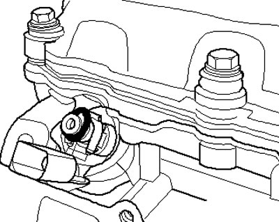
9.5. Removing the sealing ring
(View the original on the website: SKODABOOK.RU)
6. Screw the T10133/3 sliding hammer onto the 0133/15 pullers, insert this puller into the groove (see illustration 9.6a) on the injector and pull out the injector, slightly knocking it out (see illustration 9.6b).
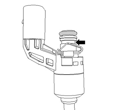
9.6a. Groove on the injector
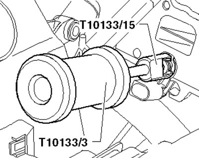
9.6b. Removing the injector
7. After removing the injector, it is necessary to replace its Teflon seal and support washer. To remove the seal, cut it with a knife, avoiding the knife touching the injector. To install the seal, clean the injector and slide the seal into the groove on the injector using a suitable sizing sleeve. To remove the thrust washer, remove the sealing ring (1 in the illustration), cut the washer (2) with small nippers and remove it. Then remove the spring element (3) and install a suitable support plate in its place. Press on a new thrust washer using a suitable bushing, install a new spring element and a new sealing ring. Lubricate the O-ring with engine oil. Do not lubricate the Teflon seal!
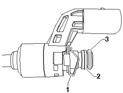
9.7. Spring element (1), support washer (2) and sealing ring (3)
8. Thoroughly clean the injector seat in the cylinder head with a nylon brush and press the injector into the cylinder head by hand until it stops (see illustration). The injector should fit easily; if necessary, wait until the seal has compressed sufficiently.
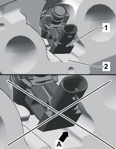
9.8. Installing the injector
9. Further installation is carried out in reverse order.
Engine 1.4 l
10. The fuel distribution line is built into the lower part of the intake manifold. The details of the injector installation are shown in the illustration.
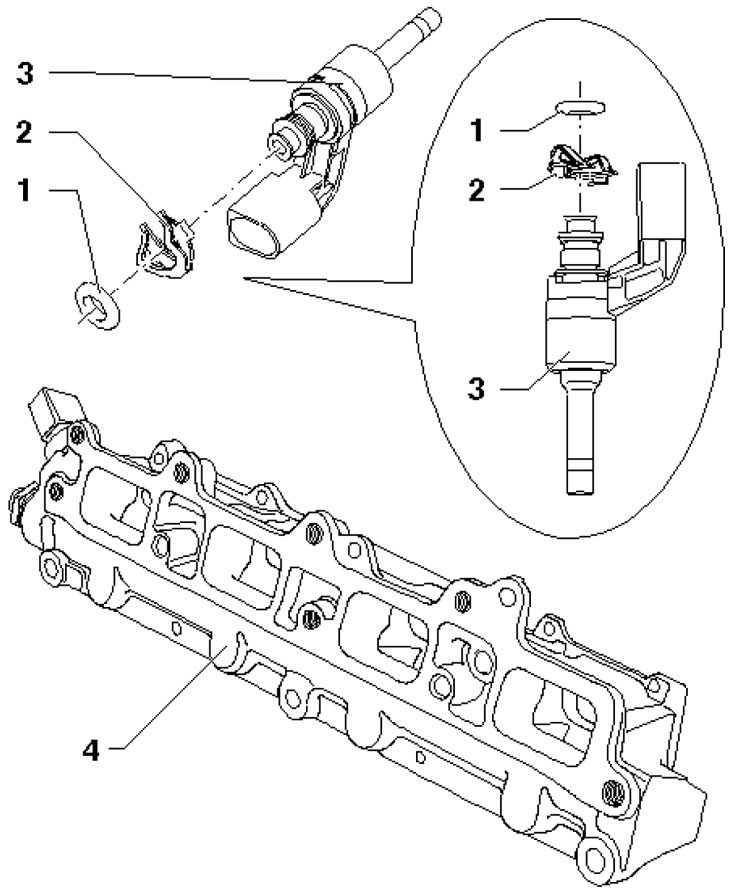
9.10. Injector and Fuel Rail/Lower Intake Manifold Installation Details 1. O-ring, subject to replacement, lightly lubricate with engine oil before installation; 2. Spring element, after removal, part 4 should be replaced; 3. Injector, after removal, replace the Teflon seal and support washer; 8. Lower part of the intake manifold
Petrol engines 1.8 l
11. The installation details of the fuel injection system components are shown in the illustration.
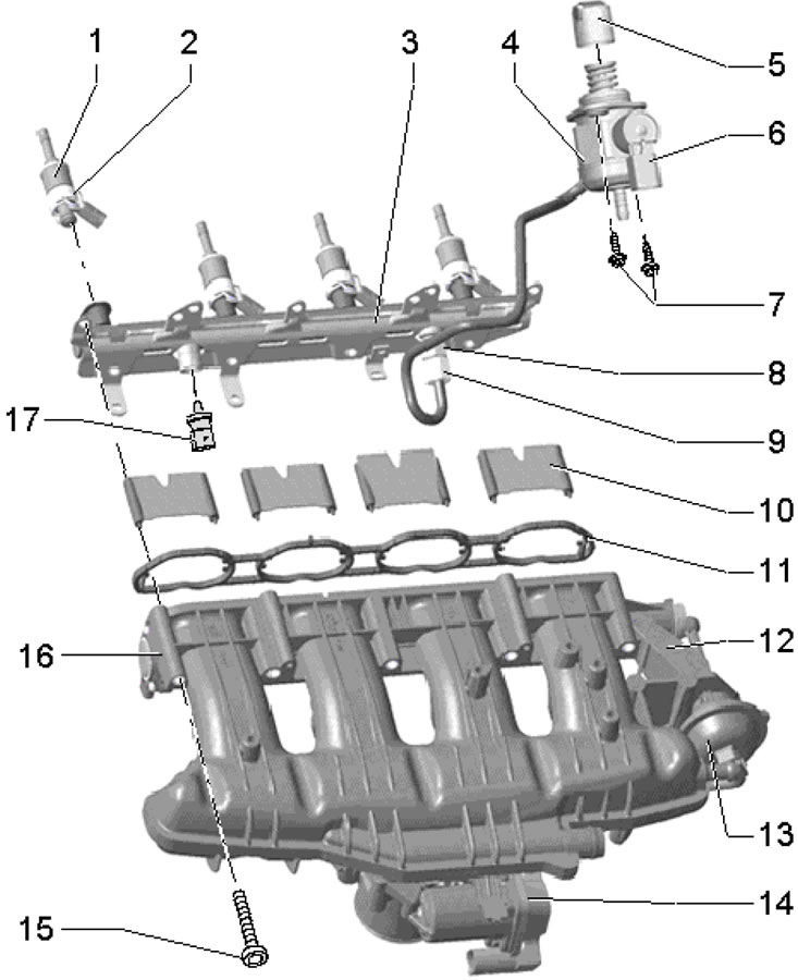
9.11. Fuel injection system component installation details (1.8 l models) 1. Injector, with replaceable Teflon seal and O-rings; 2. Support ring; 3. Fuel distribution line; 4. High-pressure fuel pump, with valve 6, the pressure line is fastened with a force of 17 Nm; 5. Roller pusher; 6. Solenoid valve "N276" for fuel pressure regulation; 7. Fuel injection pump mounting bolts, subject to replacement, 10 Nm; 8. Fuel supply line connection, subject to replacement, 25 Nm; 9. Fuel supply line union nut, 18 Nm; 10. Air flow control flaps; 11. Gasket, subject to replacement; 12. Inlet manifold; 13. Vacuum block (installation element) intake manifold flap valve; 14. Throttle module "J338", with actuator "G186" and position sensors No. 1 "G187" and No. 2 "G188"; 15. Intake manifold mounting bolts, 3 Nm, then 9 Nm; 16. Sensor "G336" of the flap position of the intake manifold, when replacing, adapt the ECM; 17. Fuel pressure sensor "G247", 25 Nm, lubricate the threads with engine oil before tightening
12. The fuel distribution line is removed together with the intake manifold, after which they can be separated from each other (see Section 7). The details of the injector installation are shown in the illustration; their removal and installation are described below.
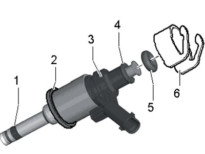
9.12. Injector components 1. Teflon combustion chamber seal, replaceable, installed without lubrication; 2. Intermediate ring, cone should face the valve; 3. Injector; 4. Support ring; 5. O-ring, subject to replacement, lubricate with engine oil before installation; 6. Support element (to transmit the force of the fuel distribution line and hold the injector in the cylinder head)
13. Remove the intake manifold and fuel rail assembly, plug the intake ports with a clean cloth (see Section 7).
14. Remove the support elements (And in the illustration) and disconnect the injector connectors (arrows).
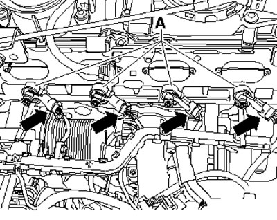
9.14. Injector support elements and connectors
15. Install the T10133/2A puller with the T10133/16 device into the injector groove and pull out the injector by screwing in the bolt (1 in the illustration).
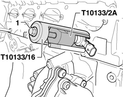
9.15. Removing the injector
Note: Please pay attention to the spacer ring.
16. Clean the injector mounting holes thoroughly with a nylon brush. If an open intake valve prevents this, turn the crankshaft.
17. Replace the Teflon seal (see description for 1.2L engine above), sealing ring (5 in illustration 9.11) and the support ring (4) of the injector.
Note: The Teflon seal is installed without lubrication.
18. Assemble the injector using the parts from the repair kit. Press it by hand as far as possible into the hole in the cylinder head without using oil or grease. Make sure the injectors are positioned correctly (see illustration).
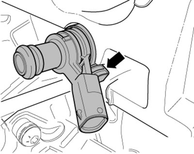
9.18. Installation position of the injector
19. If you cannot install the injector by hand, use the T10133/2A puller with the T10133/3 hammer (see illustration).
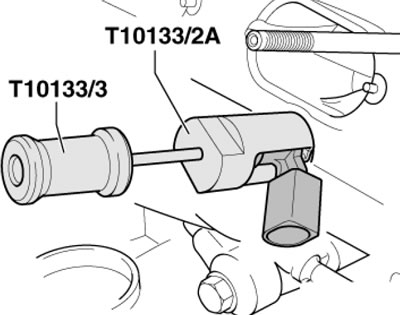
9.19. Installing the injector
20. Install the support element on the injector and lightly moisten the fuel injection pump sealing rings with engine oil.
21. Install the intake manifold and fuel rail assembly.
Diesel engines 2.0 l (CFHC, CFJA and CLCB)
22. The installation details of the fuel injection system components are shown in the illustration.
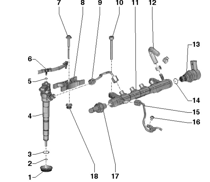
9.22. Installation details of fuel injection system components for 2.0L engines (CFHC, CFJA and CLCB), except for fuel injection pump 1. Seal, in the cylinder head cover; 2. Copper washer, subject to replacement; 3, 5, 14. Sealing ring, subject to replacement; 4. Nozzle; 6. Return fuel line, from injectors to fuel tank, with 2.0 bar check valve, do not disassemble; 7. Bolt, subject to replacement, 8 Nm, then tighten to an angle of 180°; 8. Retaining part, installed only in the same place; 9. Pressure line, between line 11 and injector, 15 Nm, then tighten to an angle of 60°; 10. Bolt, 22 Nm; 11. Fuel distribution line; 12. Return fuel hose; 13. Valve "N276" fuel pressure regulation, 80 Nm, after removal must be replaced; 15. Pressure line, between the high-pressure fuel pump and the main line 11, 15 Nm, then tighten to an angle of 60'; 16. Bolt, 8 Nm; 17. Fuel pressure sensor "G247", 100 Nm, must be replaced after removal; 18. Bushing in cylinder head cover
Caution: After removing fuel system components, air must be bled from the system before starting the engine (see Section 3).