



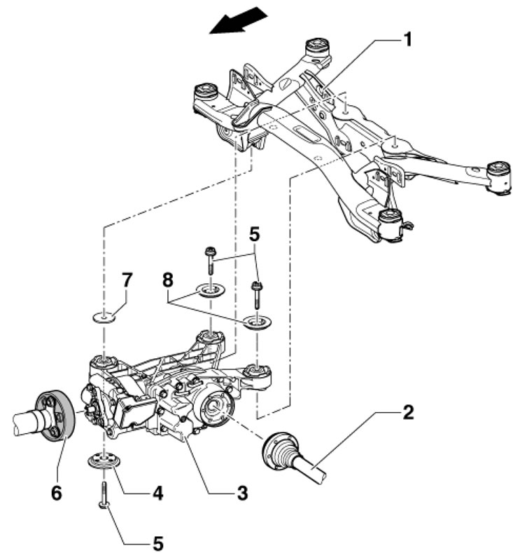
12.1. Rear final drive installation details Arrow Direction of movement; 1. Rear subframe; 2. Drive shaft; 3. Rear final drive; 4, 8. Lock washers; 5. Bolts, 3 pcs.; 6. Cardan shaft; 7. Washer, between parts 3 and 1, some models use 2 washers
2. Lift the luggage compartment floor covering and remove the two plugs (And in the illustration) and unscrew the bolts (B) located underneath them that secure the main gear housing to the subframe. It is recommended to use the T10061 head. Re-use of these bolts is not permitted.
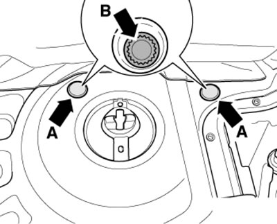
12.2. Plugs and bolts accessible from the luggage compartment
3. Follow the steps described in paragraphs 3-9 Section 11.
4. To prevent damage to the rear left suspension height sensor (1 in the illustration), disconnect the connector, remove the sensor fastener and place it on the lower suspension arm (A).
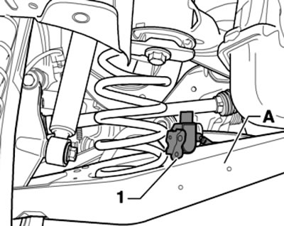
12.4. Sensor G76 on the rear suspension arm
5. Unscrew the fasteners of both drive shafts to the rear final drive (see Section 4). Remove the rear suspension stabilizer bar (see Chapter 10). To loosen/tighten the top bolt (top arrow in the illustration) stabilizer clamp, grasp the corresponding drive shaft in the flange shaft of the rear main gear and press it upward.
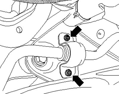
12.5. Stabilizer clamp mounting bolts
6. Place a suitable wooden block (And in the illustration) on a universal support, support the rear main gear with a VAG1383A transmission jack, fasten them together with straps, unscrew the bolt (B) on the front bracket and remove the washer (C) at the top of the bracket.
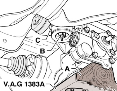
12.6. Bolt (B) of the front bracket
[This material is published on the portal: www.skodabook.ru]
7. Carefully raise the rear final drive (And in the illustration) in the direction of the arrow (1) and pull it forward slightly. At the same time, move the rear final drive at the rear to the right (arrow 2), remove the left drive shaft (B) from the flange and carefully remove it downwards.
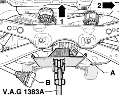
12.7. Separating the left drive shaft
8. Shift the rear final drive (And in the illustration) to the left in the direction of the arrow, remove the right drive shaft (B) from the flange and carefully lower it down.
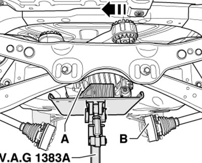
12.8. Separating the right drive shaft
9. Tilt the rear final drive as shown in the illustration and at the same time lower it slightly.
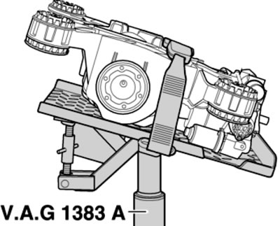
12.9. Position during removal/installation
10. Disconnect the connector (And in the illustration) aWD control unit "J492" and disconnect the ventilation lines (arrows).
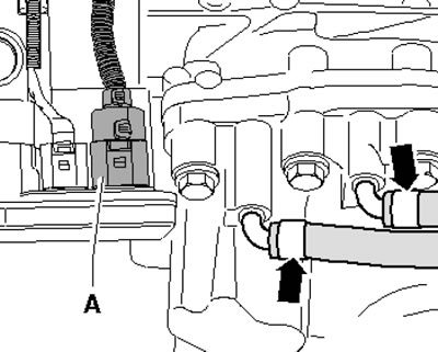
12.10. Rear main gear connections
11. Lower the final drive even lower and move it forward.
12. Secure the final drive to the jack and bring it to the installation position (see illustration 12.9).
13. Raise the final drive and slide the rear supports (see illustration) above the subframe. Make sure that the rubber-to-metal bearings have lock washers.
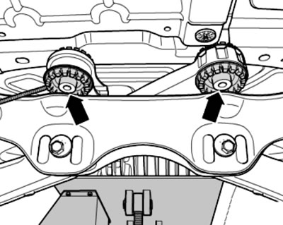
12.13. Installing the main gear
14. Shift the rear final drive (And in illustration 12.8) to the left in the direction of the arrow and install the right drive shaft (B) on the flange.
15. Carefully raise the rear final drive (And in illustration 12.7) in the direction of the arrow (1) and pull it forward slightly. At the same time, move the rear final drive at the rear to the right (arrow 2) and install the left drive shaft (B) on the flange.
16. Connect the connector (And in the illustration 12.10) aWD control unit "J492" and connect the ventilation lines (arrows). Move the rear final drive to the installation position on the jack.
17. Place the washer on the front support (With in the illustration), hand tighten bolt (B) and remove the transmission jack.
18. Tighten two new bolts through the holes in the luggage compartment and plug these holes with plugs.
19. Tighten the rear final drive fastener from below (see illustration 10.4).
20. Install and secure the propeller shaft (see Section 7).
21. Install the anti-roll bar (see Chapter 10).
22. Secure the drive shafts (see Section 4).
23. Tighten the new rocker support to transmission bolts.
24. Adjust the intermediate bearing of the cardan shaft without tension and secure it.
25. Install the exhaust system.
26. Install the rear suspension height sensor. Using the scan tool, apply the basic settings to adjust the headlight level.
27. Finally, check and, if necessary, adjust the level of working fluids in the Haldex clutch and in the rear final drive.