



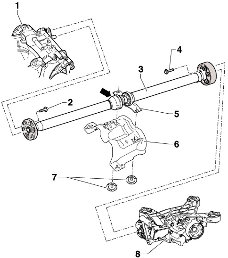
7.1. Cardan shaft installation details 1. Angular transmission 2 Bolts M 10x30, 3 pcs., 60 Nm; 3. Cardan shaft, when installing, bearing 5 should be behind the hinge (arrow); 4. Bolts M10x45, 3 pcs., 60 Nm; 5. The intermediate bearing must be set without tension; 6. Heat shield; 7. Bolt, 25 Nm; 8. Rear final drive
2. Before removing, mark the relative positions of all parts relative to each other so that they can be installed in the same position later. This will avoid any imbalance that causes noise.
3. Remove the sound insulation under the engine compartment (see Chapter 11).
4. Remove the center tunnel cross member and disconnect the exhaust system at the double clamp. Unhook the rear muffler from the hangers and remove the rear section of the exhaust system. Remove the exhaust bracket from the subframe (see illustration 5.14 Chapter 6) and tie up the exhaust pipe, preventing its flexible section from bending more than 10°.
5. Support the driveshaft with a transmission jack, placing wooden blocks between them, and secure the shaft to the jack with suitable straps.
6. Remove the bolts (1 in illustration 4.23 Chapter 6) and remove the heat shield (2) under the propeller shaft.
7. Screw in the bolts (1 in the illustration) heat shield into place by hand to secure the intermediate bearing (arrow).
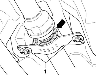
7.7. Fastening of the intermediate bearing
8. Mark the position of the cardan shaft with flexible disk relative to the output flange of the angular transmission, and then release the fastener of the cardan shaft to the output flange of the angular transmission (see illustration 5.15 Chapter 6).
9. Remove the rocker support from the transmission by unscrewing the bolts (B and C in Illustration 5.16 Chapter 6).
10. After removing the rocker support from the manual transmission, the power unit tilts slightly forward, so be careful not to damage the gasket (see illustration 5.17 Chapter 6) in the flange of the cardan shaft.
11. Check that there are color marks on the flexible disk of the cardan shaft and on the flange of the Haldex coupling (see accompanying illustration). Apply these marks if necessary.
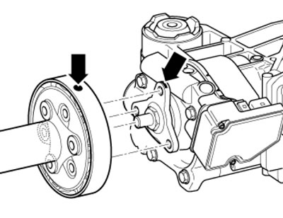
7.11. Markings on the propeller shaft and on the Haldex coupling flange
12. Remove the bolts securing the propeller shaft to the Haldex coupling flange (see illustration).
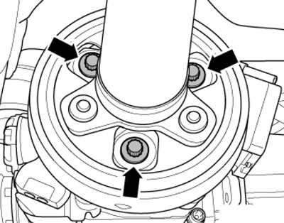
7.12. Bolts for fastening the cardan shaft to the Haldex coupling
(Original text is located on skodabook.ru)
13. Ask an assistant to hold the drive shaft. Remove the intermediate bearing mounting bolts (see illustration 7.7) and move the shaft forward, slightly pushing the power unit forward. Then pull the propeller shaft out of the centering pin on the rear final drive and pull the shaft out of the centering pin on the angular transmission. Do not tilt the cardan shaft, move it horizontally from the centering studs to avoid damaging the gaskets (see illustration 5.17 Chapter 6) in the flanges of the cardan shaft. After removal, do not bend the drive shaft.
14. Installation is carried out in reverse order. Install the shaft so that all marks made during removal match.