
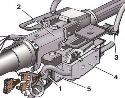
Circuit breaker connectors (castle) ignition
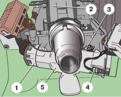
1 – connecting block of the ignition switch; 2 - steering column; 3- «mass» the wire; 4 - connecting block of the immobilizer; 5 - ignition lock housing
Fastening of a casing of a cardan shaft of a steering column
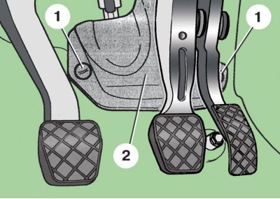
1 - plastic nuts; 2 – a casing of a cardan shaft of a steering column
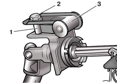
Fastening of a shaft of a steering column to a shaft of a driving gear wheel of the steering mechanism
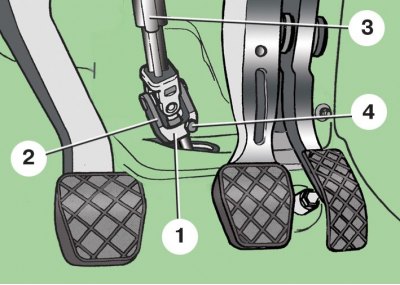
1 - the shaft of the drive gear of the steering mechanism; 2 - fork cardan joint; 3 – cardan shaft of a steering column; 4 - coupling bolt
Mounting the wiring harness on the steering column on the left side
1 - wiring harness going to the switch (castle) ignition; 2 - holder; 3 – additional holder; 4 - steering column
Mounting the wiring harness on the steering column on the right side
1 - wiring harness; 2 - steering column; 3 – additional holder; 4 – holder cover; 5 - holder
Marking the relative position of the upper and lower parts of the steering column shaft
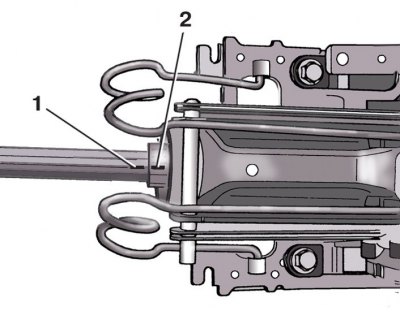
1 – a label on the bottom part of a shaft of a steering column; 2 – a label on the top part of a shaft of a steering column
Steering column assembly
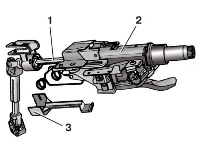
1 - the lower part of the steering column; 2 – the top part of a steering column; 3 - transport lock
Rear steering column mount
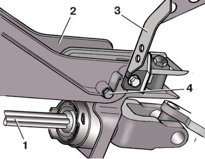
1 - steering column shaft (rear end); 2 – an arm of fastening of a steering column; 3 - damper; 4 - bolt
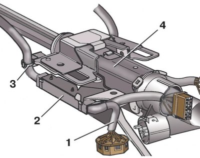
Steering column mount
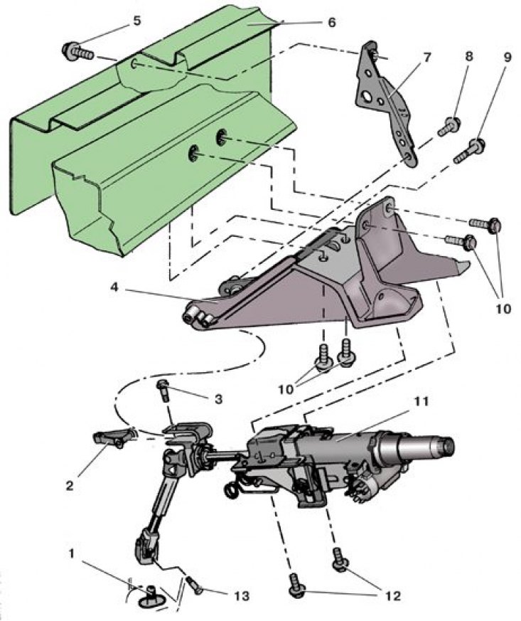
1 - the shaft of the drive gear of the steering mechanism; 2 - bushing holder; 3 – a bolt of fastening of the holder of plugs; 4 – an arm of a steering column; 6 - drainage casing; 7 - damper; 5, 8, 9, 10, 12 - bolts; 11 – steering column; 13 - coupling bolt
Sleeve holder fastening
1 - bushing holder; 2 - bolt; 3 - fork on the steering column
Attention! The steering column cannot be repaired; in the event of a malfunction, it must be replaced as an assembly.
Removing
1. Disconnect the wire from the terminal «-» battery.
2. Remove the glove box from the driver's side.
3. Remove the steering column switch (see subsection 10.11).
4. Disconnect block 1 (see fig. Circuit breaker connectors (castle) ignition) with switch wires (castle) ignition.
5. Disconnect block 4 with immobilizer wires.
6. Disconnect from steering column «mass» wire 3.
7. Loosen the two plastic nuts 1 (see fig. Fastening of a casing of a cardan shaft of a steering column) fastenings of a casing 2 cardan shaft of a steering column and remove a casing.
8. Loosen pinch bolt 4 (see fig. Fastening of a shaft of a steering column to a shaft of a driving gear wheel of the steering mechanism) cardan yokes.
9. Remove upwards the fork 2 of the cardan joint from the shaft 1 of the drive gear of the steering mechanism.
10. Opening the holder cover 2 (see fig. Mounting the wiring harness on the steering column on the left side) on the left side, remove the wiring harness 1 from it, going to the switch (castle) ignition.
11. Slide in the direction indicated by the arrow and remove additional holder 3 with harness 1 from the steering column.
12. Opening cover 4 (see fig. Mounting the wiring harness on the steering column on the right side) holder, remove the wiring harness 1 from it.
13. Slide in the direction indicated by the arrow and remove additional holder 3 with harness 1 from the steering column.
14. Mark from below the relative position of the upper and lower parts of the steering column shaft (see fig. Marking the relative position of the upper and lower parts of the steering column shaft).
15. Fasten the top 2 with wire (see fig. Steering column assembly) and lower 1 part of the steering column.
Attention! If you intend to reinstall the removed steering column, do not separate its upper and lower parts, as their splines have run in to each other and play may appear in a different position of the splines in the connection. In addition, grease-lubricated shafts can become contaminated with dirt.
16. Remove rear bolt 4 (see fig. Rear steering column mount) steering column mounts.
17. Remove the two front bolts 12 (see fig. steering column mount) steering column mounts.
18. Remove the steering column 11.
19. Replace holder 1 (see fig. Sleeve holder fastening) with worn or damaged bushings. To do this, unscrew the fastening bolt 2 and remove the holder 1 from the fork 3 on the steering column.
20. When replacing the steering column, remove the switch from it (lock) ignition, since the steering column is delivered in spare parts only with the switch housing.
Installation
1. Install holder 1 if necessary (see fig. Sleeve holder fastening) bushing in the fork 3 on the steering column and fix it with bolt 2.
2. Install a switch if necessary (lock) ignition.
3. Install the steering column 11 (see fig. steering column mount) on the bracket and screw the rear bolt 9 of its fastening by hand, without tightening (bolt head must be on the right side).
4. Screw in the front bolts 12 for fastening the steering column, having previously aligned the holes for them on the bracket 4 and the steering column.
5. Tighten a back bolt 9 fastenings of a steering column the demanded moment.
6. Remove transport lock 3 (see fig. Steering column assembly) on a new column or wire - on the old one.
7. Next, assemble in the reverse order, replacing the coupling bolt 13 (see fig. steering column mount) new universal joint forks.
Tightening torques, Nm
| Bolt of fastening of the holder of plugs in a fork of a steering column | 7 |
| Front steering column mounting bolts | 23 |
| Rear steering column bolt | 20 |
| Coupling bolt for cardan joint | 20, then turn 90° |