



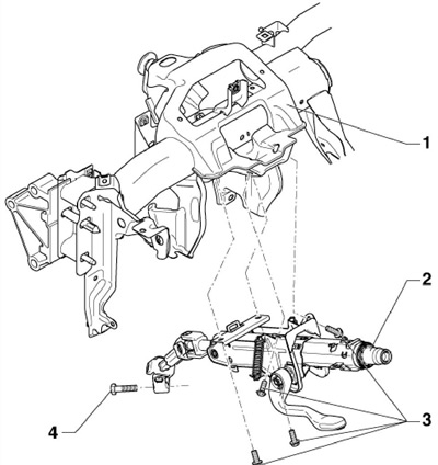
15.1 Steering column parts
1 Instrument panel beam, with bracket for steering column
2 Steering column
3 Bolt M8x30, 20 Nm
4 Bolt M8x35, subject to replacement, 30 Nm
2. Set the front wheels to the straight-ahead position.
3. Lower and extend the steering column to the stop and fully extend it, then lock it.
4. Remove the driver's airbag (see Chapter 12). Set the steering wheel to the straight-ahead position, unscrew the bolt (2 on the accompanying illustration), mark the position of the steering wheel relative to the steering column shaft (4) and remove it.
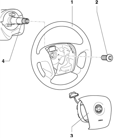
15.4 Steering wheel installation details
1 Steering wheel
2 Bolt, 50 Nm, can be used no more than 5 times (mark each time after tightening)
3 Airbag
4 Steering column shaft
5. Remove both steering column covers and the driver's storage compartment (see Chapter 11).
6. Remove the driver's knee airbag (see Chapter 12), then remove the air duct in the driver's footwell.
7. Disconnect the electrical connector of the steering column electronic control unit "J527".
8. Disconnect the immobilizer reading coil wiring connector (remove the ignition lock cylinder from the ignition switch). When the lock cylinder is removed, do not move the ignition switch, otherwise it will become locked and will need to be replaced. After disconnecting the immobilizer wiring connector, install the lock cylinder.
9. Remove the ground wire from the steering column (1 on the accompanying illustration) and a guide (2) for electrical wiring.
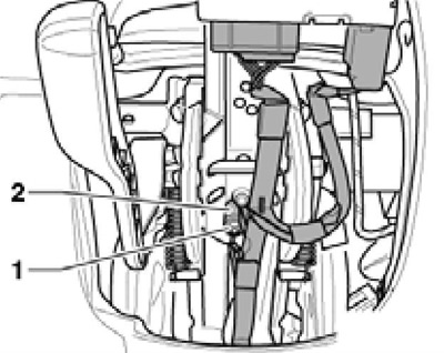
15.9 Ground wire (1) and guide (2)
10. Remove the wiring guide from the steering column (1 on the accompanying illustration), releasing it from the clamps (arrows).
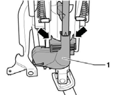
15.10 Guide
11. Remove the screws securing the cover behind the pedals (see illustration 5.2).
12. Unscrew the bolt (1 in illustration 5.3) and remove the joint (2) from the steering gear.
13. Remove the bolts (1-4 on the accompanying illustration) steering column mounts and remove it.
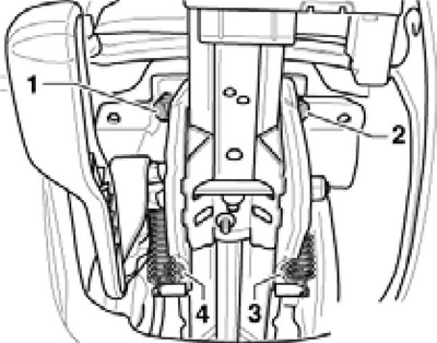
15.13 Steering column mounting bolts
14. The steering column should be carried with both hands, without bending it, holding it by the top and in the hinge area (see accompanying illustration). In this case, the locking lever must always be facing upwards so that the connected shafts do not touch the lock.
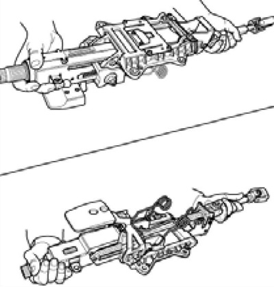
15.14 Correct carrying of the steering column
15. Position the steering column on the instrument panel beam and tighten by hand (1-4 in illustration 15.13). Tighten bolts (1 and 2) completely, making sure the steering column is flush with the instrument panel beam. Then tighten bolts (3 and 4).
16. Position the hinge (2 in illustration 5.3) on the steering gear pinion and tighten the bolt (1).
17. Install the electrical wiring guides (see illustrations 15.10 and 15.9), secure the ground wire.
18. Connect the wiring connectors of the "J527" unit and the immobilizer.
19. Install the air duct in the driver's footwell, then the driver's knee airbag (see Chapter 12).
20. Install the steering column covers.
21. Install the steering wheel and driver's airbag.
22. Install the driver's storage box and the trim behind the pedals.
23. Apply the basic settings for the G85 steering wheel angle sensor.