Removing
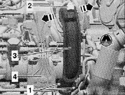
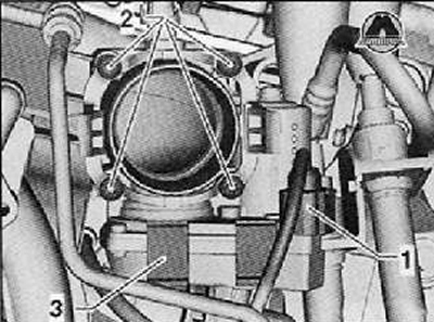
1. Unscrew the fastening screws (1), shown in the figure below, then detach the mounting clip.
2. Disconnect the wiring harness connector (2) from charge pressure sender G31 to intake air temperature sender 2 G299 as shown in the figure below.
3. Unlock the locks in the direction of the arrow, disconnect the pressure pipe (3) first from the throttle valve module J338 and then from the turbocharger.
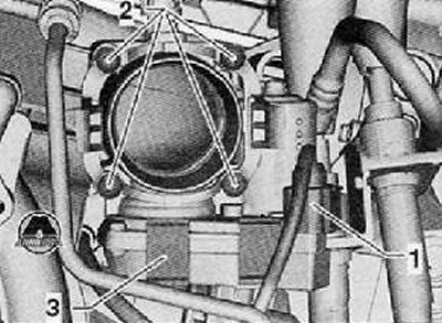
4. Disconnect the wiring harness connector (1) from throttle valve module J338. as shown in the picture below.
5. Unscrew the fastening screws (2) and remove the throttle valve module J338 from the intake manifold.
Installation
1. Insert a new O-ring into the intake manifold groove.
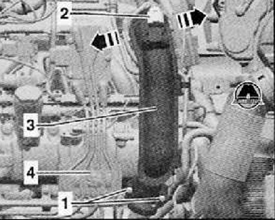
2. Install throttle module (3) together with an adapter (2) and fixing screws (1) to the intake manifold (4), as shown in the figure below.
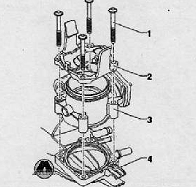
3. Tighten the fastening screws (2) with a tightening torque of 7 Nm as shown in the figure below.
4. Install the wiring harness connector (1) to throttle module (3), as shown in the figure below.
Note. Lightly lubricate the O-rings on the turbocharger and in the pressure pipe with engine oil before proceeding with installation.
5. Install the pressure pipe of the intake system (3) on the turbocharger as shown in the figure below.
6. Install pressure connection (3) to the throttle module. The retaining clips should then snap into place.
7. Tighten the fastening screws (1) mounting clamp with a tightening torque of 7 Nm.
8. Install the wiring harness connector (2) charge pressure sender G31 with intake air temperature sender 2 G299 as shown in the figure below.
When installing a new throttle module
9. Reset the learned values and adapt the electronic engine control unit J623 to the throttle control mechanism.
Cleaning the Throttle Module Assembly
Note.
- Observe safety measures when working on the power system.
- If a new engine control unit J623 is installed. then it is necessary to adapt the throttle control mechanism. Adaptation can only be carried out with a new or cleaned throttle control mechanism, since carbon contamination in the places where the closed throttle valve touches the fitting can lead to distorted adaptation values.
- Be extremely careful when cleaning to avoid scratching the throttle bore.
1. Remove throttle module assembly (see relevant section in this chapter).
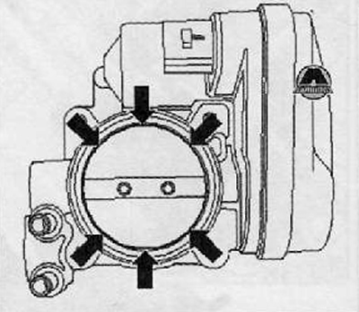
2. After opening the throttle with your hand, block it in the open position with a suitable object (e.g. plastic or wooden wedge) (arrow), as shown in the figure below.
Attention. Acetone is flammable. Observe the safety regulations and safety instructions for handling flammable liquids. Do not use compressed air to clean the throttle body. Safety goggles and protective clothing must be worn to avoid injury and skin contact with fuel.
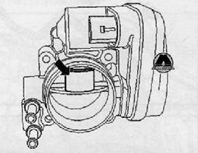
3. Thoroughly clean the throttle valve opening with ordinary acetone and a brush, especially in the area where the throttle valve is attached to the walls (arrows).
4. Use a clean, lint-free rag to wipe the cleaned throttle body surface.
5. Allow the acetone to dry out completely and install the cleaned throttle module back.