



Power supply and engine management system Skoda Rapid 1

Power system — appearance (engine 1.2 l MPI)
1. Vacuum control valve (forced exhaust gas recirculation system PCV) 2. Fuel injectors 3. Solenoid valve 1 activated carbon tank 4. Engine speed sensor 5. Intake manifold air pressure sensor and intake air temperature...
1. Vacuum control valve (forced exhaust gas recirculation system PCV) 2. Fuel injectors 3. Solenoid valve 1 activated carbon tank 4. Engine speed sensor 5. Intake manifold air pressure sensor and intake air temperature...

Measuring the quantity of injected fuel (engine 1.2 l MPI)
Note. Necessary special devices, control and measuring devices, as well as auxiliary means: Remote control device such as (VAG 1348/ZA). Adapter (adapter). (V.A.G 1348/3-2). digital potentiometer, (V.A.G 1630)....
Note. Necessary special devices, control and measuring devices, as well as auxiliary means: Remote control device such as (VAG 1348/ZA). Adapter (adapter). (V.A.G 1348/3-2). digital potentiometer, (V.A.G 1630)....

Ignition system (engine 1.2 l MPI)
1. Ignition coil with output power stage 2. Ignition coil harness connector 3. Knock sensor wiring harness connector 4. Knock sensor mounting bolt, tightening torque when installing 20 Nm 5. Knock sensor 6. Camshaft...
1. Ignition coil with output power stage 2. Ignition coil harness connector 3. Knock sensor wiring harness connector 4. Knock sensor mounting bolt, tightening torque when installing 20 Nm 5. Knock sensor 6. Camshaft...

Removal and installation of ignition coils — removal and installation (engine 1.2 l MPI)
Note. Necessary special devices, control and measuring devices, as well as auxiliary means: Assembly tool -T10118-. Puller -T10094A-. Removing 1. Fit puller -T10094A- on the ignition coil with power output stage in the...
Note. Necessary special devices, control and measuring devices, as well as auxiliary means: Assembly tool -T10118-. Puller -T10094A-. Removing 1. Fit puller -T10094A- on the ignition coil with power output stage in the...

Fuel tank — appearance (engine 1.2 l MPI)
1. Fuel tank assembly 2. O-ring 3. Fuel pump module assembly 4. Mounting nut 5. Fuel return line 6. Pressure fuel line 7. Bypass hose 8. Lid 9. Fuel filler head 10. Connection «masses» 11. O-ring 12. Vent valve 13....
1. Fuel tank assembly 2. O-ring 3. Fuel pump module assembly 4. Mounting nut 5. Fuel return line 6. Pressure fuel line 7. Bypass hose 8. Lid 9. Fuel filler head 10. Connection «masses» 11. O-ring 12. Vent valve 13....

Pumping fuel from the fuel tank (engine 1.2 l MPI)
Note. In case of failure of the fuel pump, it is necessary to extract the fuel using a fuel suction device (VAS 5190). Note. Observe the rules of cleanliness when working on the fuel supply or fuel injection system. 1....
Note. In case of failure of the fuel pump, it is necessary to extract the fuel using a fuel suction device (VAS 5190). Note. Observe the rules of cleanliness when working on the fuel supply or fuel injection system. 1....

Fuel pump module assembly (engine 1.2 l MPI)
Removing Note The ignition must be turned off and the key removed from the ignition. The fuel tank can be filled up to a maximum of 3/4. 1. Remove the rear seat cushion assembly (for details, see the relevant section in...
Removing Note The ignition must be turned off and the key removed from the ignition. The fuel tank can be filled up to a maximum of 3/4. 1. Remove the rear seat cushion assembly (for details, see the relevant section in...

Removing and installing fuel gauge sensor (engine 1.2 l MPI)
Removing Note. Two types of fuel gauge sensor are installed in cars. 1. Remove the fuel pump (see the relevant section in this chapter). 2. Unlock and remove wires (3) And (4), shown in the figure below. 3. Pry up the...
Removing Note. Two types of fuel gauge sensor are installed in cars. 1. Remove the fuel pump (see the relevant section in this chapter). 2. Unlock and remove wires (3) And (4), shown in the figure below. 3. Pry up the...

Fuel tank — removal and installation (engine 1.2 l MPI)
Removing Note. Necessary special devices, control and measuring devices, as well as auxiliary means: Stand for removing and installing the engine and gearbox -VA G 1383A -. Note. The ignition must be turned off and the...
Removing Note. Necessary special devices, control and measuring devices, as well as auxiliary means: Stand for removing and installing the engine and gearbox -VA G 1383A -. Note. The ignition must be turned off and the...

Elements of the power supply and control system (1.2 l TSI engine)
1. Engine oil pressure sensor 2. Solenoid valve 3. Solenoid valve 1 activated carbon filter 4. Intake manifold pressure sensor and intake air temperature sensor 5. Fuel pressure regulator valve 6. Knock sensor 7. Hall...
1. Engine oil pressure sensor 2. Solenoid valve 3. Solenoid valve 1 activated carbon filter 4. Intake manifold pressure sensor and intake air temperature sensor 5. Fuel pressure regulator valve 6. Knock sensor 7. Hall...

Fuel rail and intake manifold (1.2 l TSI engine)
1. Air connection for charge air 2. Mounting bolt, installation torque 7 Nm 3. Locking clip 4. Fuel rail 5. Fuel pressure sensor 6. Fuel rail mounting bolt, tightening torque when installing 20 Nm 7. Union nut,...
1. Air connection for charge air 2. Mounting bolt, installation torque 7 Nm 3. Locking clip 4. Fuel rail 5. Fuel pressure sensor 6. Fuel rail mounting bolt, tightening torque when installing 20 Nm 7. Union nut,...

Removal and installation of the throttle valve (1.2 l TSI engine)
Removing 1. Unscrew the fastening screws (1), shown in the figure below, then detach the mounting clip. 2. Disconnect the wiring harness connector (2) from charge pressure sender G31 to intake air temperature sender 2...
Removing 1. Unscrew the fastening screws (1), shown in the figure below, then detach the mounting clip. 2. Disconnect the wiring harness connector (2) from charge pressure sender G31 to intake air temperature sender 2...

High pressure fuel pump — appearance (1.2 l TSI engine)
1. Mounting bolt tightening torque when installing 15 Nm 2. Fuel hose (low pressure, with spring clamps) 3. Spring clamp 4. Union nut, 25 Nm (when loosening, hold on to the connection on the high-pressure pump) 5. Union...
1. Mounting bolt tightening torque when installing 15 Nm 2. Fuel hose (low pressure, with spring clamps) 3. Spring clamp 4. Union nut, 25 Nm (when loosening, hold on to the connection on the high-pressure pump) 5. Union...

High pressure fuel pump — removal and installation (1.2 l TSI engine)
Removing Attention. The engine power system is divided into a high pressure part (with a maximum pressure of 12 MPa = 120 bar) and low pressure part (with a pressure of approx. 0.6 MPa = b bar). Before opening the high...
Removing Attention. The engine power system is divided into a high pressure part (with a maximum pressure of 12 MPa = 120 bar) and low pressure part (with a pressure of approx. 0.6 MPa = b bar). Before opening the high...

Removal and installation of fuel injectors (1.2 l TSI engine)
Note. When working on the power supply system, safety precautions must be observed. When working on the power supply system, cleanliness rules must be observed. Before proceeding with assembly work, ensure that safety...
Note. When working on the power supply system, safety precautions must be observed. When working on the power supply system, cleanliness rules must be observed. Before proceeding with assembly work, ensure that safety...

Replacing the Teflon O-Ring and Support Ring on the Fuel Injector (1.2 l TSI engine)
Note. When working on the power supply system, safety precautions must be observed. When working on the power supply system, cleanliness rules must be observed. Note. Necessary special devices, control and measuring...
Note. When working on the power supply system, safety precautions must be observed. When working on the power supply system, cleanliness rules must be observed. Note. Necessary special devices, control and measuring...

Electronic engine control unit (1.2 l TSI engine)
Removing Note. Before replacing the engine control unit -J623-, the identification of the control unit must first be known. When replacing, the throttle valve control unit -J338- must be cleaned before fitting the new...
Removing Note. Before replacing the engine control unit -J623-, the identification of the control unit must first be known. When replacing, the throttle valve control unit -J338- must be cleaned before fitting the new...

Ignition system — appearance (1.2 l TSI engine)
1. Wire harness guide 2. Mounting bolt, installation torque 8 Nm 3. Lid 4. Connector harness 5. Hall sensor 6. Hall sensor mounting bolt, tightening torque when installing 10 Nm 7. High voltage wire with spark plug tip...
1. Wire harness guide 2. Mounting bolt, installation torque 8 Nm 3. Lid 4. Connector harness 5. Hall sensor 6. Hall sensor mounting bolt, tightening torque when installing 10 Nm 7. High voltage wire with spark plug tip...
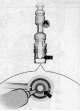
Lubrication of wire ends for spark plugs (1.2 l TSI engine)
Note. New spark plug wires are supplied already lubricated with paste. Apply a thin coat of track paste G 052 141 A2 all around to the sealing flexible tube of the spark plug wire end -arrow-. The thickness of the track...
Note. New spark plug wires are supplied already lubricated with paste. Apply a thin coat of track paste G 052 141 A2 all around to the sealing flexible tube of the spark plug wire end -arrow-. The thickness of the track...

Removing and installing engine speed sender -G28- (1.2 l TSI engine)
Note. Necessary special devices, control and measuring devices, as well as auxiliary means: Socket wrench -T10370-. Removing 1. Disconnect the wiring harness connector (arrow) from the engine speed sender -G28- as shown...
Note. Necessary special devices, control and measuring devices, as well as auxiliary means: Socket wrench -T10370-. Removing 1. Disconnect the wiring harness connector (arrow) from the engine speed sender -G28- as shown...

Fuel tank — appearance (1.4 l TSI engine)
1. Fuel tank assembly 2. O-ring 3. Fuel pump module assembly 4. Mounting nut 5. Fuel return line 6. Pressure fuel line 7. Bypass hose 8. Lid 9. Fuel filler neck 10. Connection «masses» 11. O-ring 12. Vent valve 13....
1. Fuel tank assembly 2. O-ring 3. Fuel pump module assembly 4. Mounting nut 5. Fuel return line 6. Pressure fuel line 7. Bypass hose 8. Lid 9. Fuel filler neck 10. Connection «masses» 11. O-ring 12. Vent valve 13....

Removal and installation of the fuel tank (1.4 l TSI engine)
Note. See the relevant section in this chapter (« Petrol engine 1.2 MPI »).
Note. See the relevant section in this chapter (« Petrol engine 1.2 MPI »).
Removal and installation of the fuel pump (1.4 l TSI engine)
Note. See relevant section in this chapter (« Petrol engine 1.2 MPI »).
Note. See relevant section in this chapter (« Petrol engine 1.2 MPI »).

Checking the technical condition of the fuel pump (1.4 l TSI engine)
Note. The performance of the fuel pump is checked as part of the diagnosis of the regulatory bodies. 1. Connect diagnostic, measuring and information system -VAS 505X-. 2. Turn on the ignition. 3. On the display, press...
Note. The performance of the fuel pump is checked as part of the diagnosis of the regulatory bodies. 1. Connect diagnostic, measuring and information system -VAS 505X-. 2. Turn on the ignition. 3. On the display, press...

Elements of the power system — appearance (1.4 l TSI engine)
1. Vacuum pump for brake booster 2. Intake camshaft control valve 3. Fuel injector for cylinder #1 4. Fuel injector for cylinder #2 5. Cylinder #3 fuel injector 6. Cylinder #4 fuel injector 7. Brake booster system...
1. Vacuum pump for brake booster 2. Intake camshaft control valve 3. Fuel injector for cylinder #1 4. Fuel injector for cylinder #2 5. Cylinder #3 fuel injector 6. Cylinder #4 fuel injector 7. Brake booster system...

Throttle valve assembly — removal and installation (1.4 l TSI engine)
Removing 1. Disconnect the vacuum hose from the brake booster (arrow), as shown in the figure below. 2. Loosen the clamps (1) And (2), then remove the air duct connection shown in the figure below. 3. Disconnect the...
Removing 1. Disconnect the vacuum hose from the brake booster (arrow), as shown in the figure below. 2. Loosen the clamps (1) And (2), then remove the air duct connection shown in the figure below. 3. Disconnect the...

Removal and installation of the high pressure pump (1.4 l TSI engine)
Removing Note. When working on the power supply system, safety precautions must be observed. When working on the power supply system, cleanliness rules must be observed. 1. Turn off the ignition and all electrical...
Removing Note. When working on the power supply system, safety precautions must be observed. When working on the power supply system, cleanliness rules must be observed. 1. Turn off the ignition and all electrical...

Removal and installation of fuel injectors (1.4 l TSI engine)
Note. Before proceeding with the assembly work, it is necessary to pay attention to safety measures. Note. The Geflon O-ring on the fuel injector must be replaced after each removal of the fuel injector. Note. Necessary...
Note. Before proceeding with the assembly work, it is necessary to pay attention to safety measures. Note. The Geflon O-ring on the fuel injector must be replaced after each removal of the fuel injector. Note. Necessary...

Replacing the Teflon Seal and Support Ring on the Fuel Injector (1.4 l TSI engine)
Note. Necessary special devices, control measuring devices, as well as auxiliary means: Tool kit -T10133-. 1. Remove fuel injectors (for details, see the relevant section in this chapter). 2. Thoroughly clean the fuel...
Note. Necessary special devices, control measuring devices, as well as auxiliary means: Tool kit -T10133-. 1. Remove fuel injectors (for details, see the relevant section in this chapter). 2. Thoroughly clean the fuel...

Removing and installing fuel pressure sender -G247- (1.4 l TSI engine)
Note. Necessary special devices, control and measuring devices, as well as auxiliary means: Assembly tool -T10118-. 3/8 square socket wrench", 27 mm. Removing Note. When working on the power supply system, safety...
Note. Necessary special devices, control and measuring devices, as well as auxiliary means: Assembly tool -T10118-. 3/8 square socket wrench", 27 mm. Removing Note. When working on the power supply system, safety...

Ignition system — appearance (1.4 l TSI engine)
1. Spark plug, installation torque 30 Nm 2. Conduit (Guide piece) 3. Ignition coils with final power stage 4. Mounting bolt, tightening torque when installing 10 Nm 5. Hall sender -G40- 6. O-rings 7. Knock sensor 8....
1. Spark plug, installation torque 30 Nm 2. Conduit (Guide piece) 3. Ignition coils with final power stage 4. Mounting bolt, tightening torque when installing 10 Nm 5. Hall sender -G40- 6. O-rings 7. Knock sensor 8....

Removal and installation of ignition coils (1.4 l TSI engine)
Note. Necessary devices, special control and measuring devices, as well as auxiliary means: Mounting tool-T10118-. Puller -T10094-. When installing new spark plugs: Lubricating paste -G 052 141 A2-. Note. The housing of...
Note. Necessary devices, special control and measuring devices, as well as auxiliary means: Mounting tool-T10118-. Puller -T10094-. When installing new spark plugs: Lubricating paste -G 052 141 A2-. Note. The housing of...

Removal and installation of the engine speed sensor (1.4 l TSI engine)
Note. Necessary special devices, control and measuring devices, as well as auxiliary means: Socket wrench - Т10370-. Removing Note. The installation location of the engine speed sender G28- is located under the intake...
Note. Necessary special devices, control and measuring devices, as well as auxiliary means: Socket wrench - Т10370-. Removing Note. The installation location of the engine speed sender G28- is located under the intake...

Checking the volumetric supply of the fuel pump (engine 1.6 l MPI)
Note. Supply voltage is normal. The remote control -VAG 1348/3A- is connected. 1. Unscrew the fuel filler cap. 2. Disconnect the fuel supply line (2), drain the escaping fuel into a clean rag. Attention. The fuel supply...
Note. Supply voltage is normal. The remote control -VAG 1348/3A- is connected. 1. Unscrew the fuel filler cap. 2. Disconnect the fuel supply line (2), drain the escaping fuel into a clean rag. Attention. The fuel supply...

Removal of air from the power system (engine 1.6 l MPI)
1. Remove the cover in front of the fuse holder. 2. From the fuse box under the instrument panel, remove the fuse responsible for the fuel injectors according to the circuit diagrams of the electrical equipment. 3....
1. Remove the cover in front of the fuse holder. 2. From the fuse box under the instrument panel, remove the fuse responsible for the fuel injectors according to the circuit diagrams of the electrical equipment. 3....

Elements of the engine management system 1.6 l MPI — appearance
1. Vacuum control valve (forced crankcase ventilation system) 2. Fuel injectors 3. Intake manifold air pressure sensor and intake air temperature sensor 4. Knock sensor 5. Activated carbon filter solenoid valve 6....
1. Vacuum control valve (forced crankcase ventilation system) 2. Fuel injectors 3. Intake manifold air pressure sensor and intake air temperature sensor 4. Knock sensor 5. Activated carbon filter solenoid valve 6....
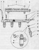
Fuel rail with fuel injectors — appearance (engine 1.6 l MPI)
1. Fuel hose 2. Fuel rail mounting screw. tightening torque when installing 7 Nm 3. Retaining clip 4. Conduit 5. Fuel rail 6. Air valve 7. Protective cap 8. Staple 9. O-ring 10. Fuel injectors
1. Fuel hose 2. Fuel rail mounting screw. tightening torque when installing 7 Nm 3. Retaining clip 4. Conduit 5. Fuel rail 6. Air valve 7. Protective cap 8. Staple 9. O-ring 10. Fuel injectors

Fuel injectors — removal and installation (engine 1.6 l MPI)
Removing Note. To avoid injury and burns, before starting any work related to the removal of fuel system elements, it is necessary to first disconnect the electrical wiring harness connector (arrow) shown in the figure...
Removing Note. To avoid injury and burns, before starting any work related to the removal of fuel system elements, it is necessary to first disconnect the electrical wiring harness connector (arrow) shown in the figure...

Checking the tightness of fuel injectors (engine 1.6 l MPI)
Attention. The power supply system is under pressure. Before opening the system, you need to put a rag under the junction. Then release the pressure by carefully disconnecting the connection. Note. This work step only...
Attention. The power supply system is under pressure. Before opening the system, you need to put a rag under the junction. Then release the pressure by carefully disconnecting the connection. Note. This work step only...

Checking the amount of fuel injected (engine 1.6 l MPI)
Note. The fuel supply pressure should be correct. The fuel injectors must be built into the fuel distributor and the fuel line connected. Fuel temperature - 15-20°С; fuel must comply with current regulations. 1. Fit...
Note. The fuel supply pressure should be correct. The fuel injectors must be built into the fuel distributor and the fuel line connected. Fuel temperature - 15-20°С; fuel must comply with current regulations. 1. Fit...

Ignition system — appearance (engine 1.6 l MPI)
1. Wiring harness connector 2. Ignition coils 3. Knock sensor wiring harness connector 4. Knock sensor 5. Knock sensor mounting bolt, tightening torque when installing 20 Nm 6. Hall sensor wiring harness connector 7....
1. Wiring harness connector 2. Ignition coils 3. Knock sensor wiring harness connector 4. Knock sensor 5. Knock sensor mounting bolt, tightening torque when installing 20 Nm 6. Hall sensor wiring harness connector 7....

Removal and installation of ignition coils (engine 1.6 l MPI)
Removing 1. Push puller -T10094 A- onto the ignition coil with power output stage in direction (arrows), as shown in the figure below. 2. Slightly remove the ignition coil with the final power stage from the cylinder...
Removing 1. Push puller -T10094 A- onto the ignition coil with power output stage in direction (arrows), as shown in the figure below. 2. Slightly remove the ignition coil with the final power stage from the cylinder...
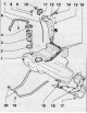
Fuel tank — appearance (1.6 TDI engine)
1. Fuel tank 2. O-ring 3. Fuel pump module 4. Union nut, installation torque 80 Nm 5. Fuel supply line 6. Drain line 7. Compensation hose 8. O-ring 9. Gravity valve 10. Fuel cap 11. Fuel filler neck 12. Connection...
1. Fuel tank 2. O-ring 3. Fuel pump module 4. Union nut, installation torque 80 Nm 5. Fuel supply line 6. Drain line 7. Compensation hose 8. O-ring 9. Gravity valve 10. Fuel cap 11. Fuel filler neck 12. Connection...
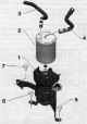
Fuel filter — appearance (1.6 TDI engine)
1. Support 2. Fuel filter assembly 3. Fuel supply hose (from fuel preheating valve) 4. Pressure fuel hose (to high pressure fuel pump) 5. Fastening bolt, tightening torque 20 Nm 6. Fastening bolt, tightening torque 20...
1. Support 2. Fuel filter assembly 3. Fuel supply hose (from fuel preheating valve) 4. Pressure fuel hose (to high pressure fuel pump) 5. Fastening bolt, tightening torque 20 Nm 6. Fastening bolt, tightening torque 20...

Removal and installation of the fuel filter (1.6 TDI engine)
Removing 1. After releasing the spring clips, disconnect the fuel hoses from the fuel filter, as shown in the figure below. 2. Move the clamps outwards, remove the fuel filter upwards. 3. Press down on the lock tabs...
Removing 1. After releasing the spring clips, disconnect the fuel hoses from the fuel filter, as shown in the figure below. 2. Move the clamps outwards, remove the fuel filter upwards. 3. Press down on the lock tabs...

Fuel heating valve connection (1.6 TDI engine)
The fuel return line leading to the fuel tank is blue or blue marked. The fuel supply line leading to the fuel filter is white or with white markings.
The fuel return line leading to the fuel tank is blue or blue marked. The fuel supply line leading to the fuel filter is white or with white markings.

Removal and installation of the fuel heating valve (1.6 TDI engine)
Removing 1. Unlock the stopper with your finger (arrow), as shown in the figure below. Pull the fuel heating valve up from the bracket on the expansion tank of the engine cooling system. Installation 1. Move the fuel...
Removing 1. Unlock the stopper with your finger (arrow), as shown in the figure below. Pull the fuel heating valve up from the bracket on the expansion tank of the engine cooling system. Installation 1. Move the fuel...

Draining fuel from the fuel filter (1.6 TDI engine)
1. Disconnect the fuel hose from the fuel filter, release the clamp of its fastening, as shown in the figure below. 2. Connect a suitable hose to the fuel filter fitting, as shown in the figure below. Then drain the...
1. Disconnect the fuel hose from the fuel filter, release the clamp of its fastening, as shown in the figure below. 2. Connect a suitable hose to the fuel filter fitting, as shown in the figure below. Then drain the...

Draining fuel from the fuel tank (1.6 TDI engine)
Note. If the fuel pump fails, the fuel must be extracted using the fuel extraction device -VAS 5190-. 1. Remove the rear seat cushion assembly (see the relevant section in chapter Body ). 2. Raise the cover of the fuel...
Note. If the fuel pump fails, the fuel must be extracted using the fuel extraction device -VAS 5190-. 1. Remove the rear seat cushion assembly (see the relevant section in chapter Body ). 2. Raise the cover of the fuel...

Removal and installation of the fuel pump (1.6 TDI engine)
Removing Note. The fuel tank must not be filled more than 3/4 of its capacity. Switch off the ignition and remove the key from the ignition switch. 1. Remove the rear seat cushion assembly. 2. Remove the fuel pump cover...
Removing Note. The fuel tank must not be filled more than 3/4 of its capacity. Switch off the ignition and remove the key from the ignition switch. 1. Remove the rear seat cushion assembly. 2. Remove the fuel pump cover...

Fuel level sensor in the tank (1.6 TDI engine)
Removing 1. Remove the fuel pump (for details, see the relevant section in this chapter). 2. Unlock and disconnect wiring harness connectors (1) (black), (2) (blue) And (3) (brown), shown in the figure below. 3....
Removing 1. Remove the fuel pump (for details, see the relevant section in this chapter). 2. Unlock and disconnect wiring harness connectors (1) (black), (2) (blue) And (3) (brown), shown in the figure below. 3....

Removal and installation of the fuel tank assembly (1.6 TDI engine)
Removing 1. Unscrew the fuel filler cap. 2. Cover the fuel filler opening with a piece of clean foam plastic so that no contaminants can get in. 3. Remove the rear seat cushion and assembly (for details, see the...
Removing 1. Unscrew the fuel filler cap. 2. Cover the fuel filler opening with a piece of clean foam plastic so that no contaminants can get in. 3. Remove the rear seat cushion and assembly (for details, see the...

Checking the operation and power of the fuel pump (1.6 TDI engine)
1. Remove the fuel pump cover under the mat. 2. Turn on the ignition. The fuel pump should run audibly. 3. Turn off the ignition. If the fuel pump is not working 4. First check if the wiring harness connector is...
1. Remove the fuel pump cover under the mat. 2. Turn on the ignition. The fuel pump should run audibly. 3. Turn off the ignition. If the fuel pump is not working 4. First check if the wiring harness connector is...

Fuel pump volumetric flow control (1.6 TDI engine)
Note. The battery voltage is at least 12.5 V. Fuel filter is ok. The fuel tank is at least ½ full. Ignition off. 1. Remove the top decorative engine cover assembly. Attention. The fuel supply line is under pressure....
Note. The battery voltage is at least 12.5 V. Fuel filter is ok. The fuel tank is at least ½ full. Ignition off. 1. Remove the top decorative engine cover assembly. Attention. The fuel supply line is under pressure....

Engine power system — appearance (1.6 TDI engine)
1. Exhaust pressure sender 1 -G450- 2. Fuel pressure sender -G247- 3. Hall sender -G40- (camshaft position sensor) 4. Connector for wiring harness for exhaust gas temperature sender -G648- 5. Fuel injectors 6. Lambda...
1. Exhaust pressure sender 1 -G450- 2. Fuel pressure sender -G247- 3. Hall sender -G40- (camshaft position sensor) 4. Connector for wiring harness for exhaust gas temperature sender -G648- 5. Fuel injectors 6. Lambda...

Engine shaft speed sensor — removal and installation (1.6 TDI engine)
Removing Note. Necessary special devices, control and measuring devices, as well as auxiliary means: Tip -T10370-. Assembly tool -T10118-. 1. Remove the bottom protection of the engine compartment. 2. Unscrew the...
Removing Note. Necessary special devices, control and measuring devices, as well as auxiliary means: Tip -T10370-. Assembly tool -T10118-. 1. Remove the bottom protection of the engine compartment. 2. Unscrew the...

Fuel rail, fuel injectors and high pressure fuel pump (1.6 TDI engine)
1. Fuel return lines (to the fuel tank) 2. Fuel pressure regulating valve -N276-, installation torque 80 Nm 3. Fuel return lines 4. Mounting bolt tightening torque when installing 10 Nm 5. High pressure fuel pump...
1. Fuel return lines (to the fuel tank) 2. Fuel pressure regulating valve -N276-, installation torque 80 Nm 3. Fuel return lines 4. Mounting bolt tightening torque when installing 10 Nm 5. High pressure fuel pump...

Removal and installation of a fuel piezoelectric nozzle (1.6 TDI engine)
Removing Note. When working on the power supply system, safety precautions must be observed. 1. Remove the top decorative engine cover. 2. If present, the soundproofing on the fuel injectors should be removed. 3....
Removing Note. When working on the power supply system, safety precautions must be observed. 1. Remove the top decorative engine cover. 2. If present, the soundproofing on the fuel injectors should be removed. 3....

Removal and installation of the fuel rail (1.6 TDI engine)
Removing Note. When working on the power supply system, safety precautions must be observed. Observe the rules of cleanliness. 1. Remove the top decorative engine cover. Note. To unscrew the union nut, the high pressure...
Removing Note. When working on the power supply system, safety precautions must be observed. Observe the rules of cleanliness. 1. Remove the top decorative engine cover. Note. To unscrew the union nut, the high pressure...

Installation of high pressure pipelines (1.6 TDI engine)
Note. Necessary special devices, control and measuring devices, as well as auxiliary means: Socket wrench-T40055-. Assembly tool -T104H-. Cleaning and degreasing agent, e.g. -D 009 401 04-. Protective goggles and...
Note. Necessary special devices, control and measuring devices, as well as auxiliary means: Socket wrench-T40055-. Assembly tool -T104H-. Cleaning and degreasing agent, e.g. -D 009 401 04-. Protective goggles and...
Fuel Pressure Control Valve Replacement (1.6 TDI engine)
Note. If the pressure in the high pressure fuel circuit is too high, open the control valve and some of the fuel from the fuel rail returns through the fuel return line back to the fuel tank. If the pressure in the high...
Note. If the pressure in the high pressure fuel circuit is too high, open the control valve and some of the fuel from the fuel rail returns through the fuel return line back to the fuel tank. If the pressure in the high...
Removing and installing fuel pressure sensor (1.6 TDI engine)
Note. The fuel pressure sender -G247- is located in the fuel distributor and measures the actual fuel pressure in the high pressure system and sends a voltage signal to the engine control unit -J623-. In the event of a...
Note. The fuel pressure sender -G247- is located in the fuel distributor and measures the actual fuel pressure in the high pressure system and sends a voltage signal to the engine control unit -J623-. In the event of a...

Removal and installation of the high pressure fuel pump (1.6 TDI engine)
Note. Necessary special devices, control and measuring devices, as well as auxiliary means: Retaining lever -T10051-. Puller -T40064-. Driving device -T40064/1-. Pins -740064/2-. Removing Note. When working on the power...
Note. Necessary special devices, control and measuring devices, as well as auxiliary means: Retaining lever -T10051-. Puller -T40064-. Driving device -T40064/1-. Pins -740064/2-. Removing Note. When working on the power...

High pressure pump pressure test (1.6 TDI engine)
Note. Necessary devices, special control and measuring devices, as well as auxiliary means: Manual vacuum pump, e.g. -VAS 6213-. Make an -adapter- from the high pressure fuel line. Condition for exercising control...
Note. Necessary devices, special control and measuring devices, as well as auxiliary means: Manual vacuum pump, e.g. -VAS 6213-. Make an -adapter- from the high pressure fuel line. Condition for exercising control...
Checking the tightness of the power system (1.6 TDI engine)
Note. Necessary devices, special control and measuring devices, as well as auxiliary means: Cleaning and degreasing agent, e.g. -D 009 401 04-. Protective goggles and gloves. Attention. Wear protective gloves and...
Note. Necessary devices, special control and measuring devices, as well as auxiliary means: Cleaning and degreasing agent, e.g. -D 009 401 04-. Protective goggles and gloves. Attention. Wear protective gloves and...

Fuel Pressure Control Valve Control (1.6 TDI engine)
Note. Necessary special devices control measuring instruments, as well as auxiliary means: Suitable auxiliary hose for connection to the fuel return line. Fuel vessel, ca. 200 ml. Note. The engine is warmed up to...
Note. Necessary special devices control measuring instruments, as well as auxiliary means: Suitable auxiliary hose for connection to the fuel return line. Fuel vessel, ca. 200 ml. Note. The engine is warmed up to...
Fuel injector reverse quantity control (1.6 TDI engine)
Note. The engine will not start. Note. Leaky start valves in the injectors can cause the engine to run rough or may cause the engine to not start. In order to check the contamination of the starting valves, and with...
Note. The engine will not start. Note. Leaky start valves in the injectors can cause the engine to run rough or may cause the engine to not start. In order to check the contamination of the starting valves, and with...

Removal, installation and control of glow plugs (1.6 TDI engine)
Note. This engine has metal glow plugs. Necessary special devices, control and measuring devices, as well as auxiliary means: Hinge wrench No. 10-3220-. Cleaning and degreasing agent, e.g. -D 009 401 04-. Protective...
Note. This engine has metal glow plugs. Necessary special devices, control and measuring devices, as well as auxiliary means: Hinge wrench No. 10-3220-. Cleaning and degreasing agent, e.g. -D 009 401 04-. Protective...
Checking the technical condition (engine 1.2 l MPI)
Oil pressure check 1. Remove the oil pressure drop switch, install (V.A.G 1342). 2. Install the oil pressure drop switch in (V.A.G 1342). 3. Start the engine (engine oil temperature - at least 80°C). oil pressure at...
Oil pressure check 1. Remove the oil pressure drop switch, install (V.A.G 1342). 2. Install the oil pressure drop switch in (V.A.G 1342). 3. Start the engine (engine oil temperature - at least 80°C). oil pressure at...
This section is available on russian, bulgarian, belarusian, ukrainian, serbian, croatian, romanian, polish, slovak, hungarian
Read similar sections on other Skoda models
➧ Power unit: Supply system Skoda Fabia 1 (1999-2007)
➧ Power unit: Fuel system Skoda Octavia 1 (1996-2004)
➧ Power unit: Power and exhaust system Skoda Superb 2 (2008-2015)
➧ Power unit: Fuel and exhaust system Skoda Favorite (1987-1994)
Link to this section in various formats
TEXTHTMLBB Code
- General information
- Faults en route
- User manual
- Maintenance and care
- Power unit
- Petrol engines
- Diesel engines
- Power and control system
- Lubrication system
- Cooling system
- Intake and exhaust system
- Transmission
- Clutch
- Mechanical gearbox
- Automatic gearbox
- Drive shafts
- Chassis (running gear)
- Front suspension
- Rear suspension
- Brake system
- Steering
- Body and interior
- Exterior (external elements)
- Interior (internal elements)
- Doors, locks and windows
- Heating and air conditioning
- Security systems
- Electrical equipment
- Equipment and devices
- Power devices
- Electrical circuits
- Electrical circuits (petrol)
- Electrical circuits (diesel)