



Brake system of the car Skoda Rapid 1

Main technical characteristics
Master brake cylinder Front brakes FS-III Front brakes FN-III Rear disc brakes С 38 Rear drum brakes
Master brake cylinder Front brakes FS-III Front brakes FN-III Rear disc brakes С 38 Rear drum brakes
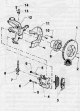
FS-III front brakes — appearance
1. Brake disc 2. Mounting screw, 4.5 Nm 3. Brake pads 4. Brake caliper assembly 5. Guide bolt 6. Plug 7. Sleeve 8. Brake hose with support, hollow mounting screw and O-rings 9. Front wheel hub instead of bearing 10....
1. Brake disc 2. Mounting screw, 4.5 Nm 3. Brake pads 4. Brake caliper assembly 5. Guide bolt 6. Plug 7. Sleeve 8. Brake hose with support, hollow mounting screw and O-rings 9. Front wheel hub instead of bearing 10....

Replacing brake pads and brake caliper (brake FS-III)
Removing 1. Remove the front wheel. Note. Mark when removing those friction linings (internal, external), to be reused. They must be re-mounted in the same place, otherwise the braking effect will be uneven. When...
Removing 1. Remove the front wheel. Note. Mark when removing those friction linings (internal, external), to be reused. They must be re-mounted in the same place, otherwise the braking effect will be uneven. When...

Removal and installation of a brake caliper (brake FS-III)
Note. Necessary special devices, control and measuring devices, as well as auxiliary means. Pedal presser, e.g. -VAG 1869/2-. Removing Note. This working method only applies to the replacement or subsequent repair work...
Note. Necessary special devices, control and measuring devices, as well as auxiliary means. Pedal presser, e.g. -VAG 1869/2-. Removing Note. This working method only applies to the replacement or subsequent repair work...

Brake caliper — appearance (brake FS-III)
1. Dust cap 2. Air bleed screw, 10 Nm (Before screwing in, lightly grease the thread with lithium-containing grease -G 052 150 A2-) 3. Bearing sleeve 4. Guide pin, 30 Nm 5. Caps 6. Disc brake caliper 7. O-ring 8. Piston...
1. Dust cap 2. Air bleed screw, 10 Nm (Before screwing in, lightly grease the thread with lithium-containing grease -G 052 150 A2-) 3. Bearing sleeve 4. Guide pin, 30 Nm 5. Caps 6. Disc brake caliper 7. O-ring 8. Piston...

Disassembly and assembly of the brake caliper (brake FS-III)
Disassembly 1. Press the piston out of the disc wheel brake caliper with compressed air. Note. Insert a wooden plank into the hole so as not to damage the piston. 2. Remove the O-ring using a plastic wedge (3409). Note....
Disassembly 1. Press the piston out of the disc wheel brake caliper with compressed air. Note. Insert a wooden plank into the hole so as not to damage the piston. 2. Remove the O-ring using a plastic wedge (3409). Note....

FN-III front brakes — appearance
1. Brake disc 2. Fastening screw, tightening torque 4.5 Nm 3. Brake pads 4. Retaining spring 5. Brake caliper mounting bracket 6. Brake caliper assembly 7. Guide bolt, tightening torque 30 Nm 8. Lid 9. Brake hose with...
1. Brake disc 2. Fastening screw, tightening torque 4.5 Nm 3. Brake pads 4. Retaining spring 5. Brake caliper mounting bracket 6. Brake caliper assembly 7. Guide bolt, tightening torque 30 Nm 8. Lid 9. Brake hose with...

Replacement of brake pads (brake FN-III)
Removing Note. If the pads are not replaced, it is necessary to note their relative position. 1. Remove the front wheels. 2. Using a screwdriver like a lever, remove the friction lining retaining spring from the disc...
Removing Note. If the pads are not replaced, it is necessary to note their relative position. 1. Remove the front wheels. 2. Using a screwdriver like a lever, remove the friction lining retaining spring from the disc...

Removal and installation of a support of the disk wheel brake mechanism of brake FN3
Note. Necessary special devices, control and measuring devices, as well as auxiliary means: Device for holding the brake pedal while bleeding the hydraulic drive system, e.g. -VAG 1869/2-. Removing Note. This working...
Note. Necessary special devices, control and measuring devices, as well as auxiliary means: Device for holding the brake pedal while bleeding the hydraulic drive system, e.g. -VAG 1869/2-. Removing Note. This working...

Brake caliper — appearance (brake FN-III)
1. Caps 2. Guide pin, 30 Nm 3. Bearing sleeve 4. Dust cap 5. Air release valve, 10 Nm (Before screwing in, lightly grease the thread with grease containing lithium -G 052 150 A2-) 6. Disc brake caliper 7. Disc brake...
1. Caps 2. Guide pin, 30 Nm 3. Bearing sleeve 4. Dust cap 5. Air release valve, 10 Nm (Before screwing in, lightly grease the thread with grease containing lithium -G 052 150 A2-) 6. Disc brake caliper 7. Disc brake...

Disassembly and assembly of the brake caliper (brake FN-III)
Disassembly 1. Press the piston out of the disc wheel brake caliper with compressed air. Note. Insert a piece of wood into the hole to prevent damage to the piston. 2. Retract the cuff with a plastic wedge (3409) from...
Disassembly 1. Press the piston out of the disc wheel brake caliper with compressed air. Note. Insert a piece of wood into the hole to prevent damage to the piston. 2. Retract the cuff with a plastic wedge (3409) from...

Rear drum brakes — appearance
1. Mounting screw, 4 Nm 2. Brake drum 3. Lid 4. Self-locking hex nut 5. Rear wheel hub assembly with bearing 6. Fixing screw 7. Brake plate with brake assembly 8. Parking brake cable 9. Rear wheel trunnion 10. Branch...
1. Mounting screw, 4 Nm 2. Brake drum 3. Lid 4. Self-locking hex nut 5. Rear wheel hub assembly with bearing 6. Fixing screw 7. Brake plate with brake assembly 8. Parking brake cable 9. Rear wheel trunnion 10. Branch...

Replacing the rear drum brake pads
Removing 1. Remove the mounting bolts and remove the rear wheel. 2. Release the parking brake. 3. Remove the brake drum. 4. Move the parking brake lever (A) back to working position using a special tool (3438), as shown...
Removing 1. Remove the mounting bolts and remove the rear wheel. 2. Release the parking brake. 3. Remove the brake drum. 4. Move the parking brake lever (A) back to working position using a special tool (3438), as shown...

Rear disc brakes — appearance
1. Fixing screw 2. Brake disc 3. Lid 4. Self-locking fastening nut, tightening torque 70 Nm + 30° 5. Rear wheel hub with bearing 6. Fastening bolt, tightening torque 30 Nm + 90° 7. Lid 8. Rear wheel trunnion 9. Rear...
1. Fixing screw 2. Brake disc 3. Lid 4. Self-locking fastening nut, tightening torque 70 Nm + 30° 5. Rear wheel hub with bearing 6. Fastening bolt, tightening torque 30 Nm + 90° 7. Lid 8. Rear wheel trunnion 9. Rear...

Replacing the rear disc brake pads
Removing 1. Remove rear wheel assembly. 2. Move the parking brake lever in the direction of the arrow and disconnect the parking brake cable from it, as shown in the figure below. 3. Compress the parking brake cable...
Removing 1. Remove rear wheel assembly. 2. Move the parking brake lever in the direction of the arrow and disconnect the parking brake cable from it, as shown in the figure below. 3. Compress the parking brake cable...

Disconnecting the brake pedal from the vacuum booster rod
1. Press the brake pedal to the stop and fix it in this position. 2. Insert special tool (T10159A) and pull it towards the driver's seat while holding the brake pedal with your hand, as shown in the figure below (the...
1. Press the brake pedal to the stop and fix it in this position. 2. Insert special tool (T10159A) and pull it towards the driver's seat while holding the brake pedal with your hand, as shown in the figure below (the...

Master brake cylinder — removal and installation
Note. The master brake cylinder is not repairable. Removing 1. Remove the decorative engine cover. 2. Remove the air filter assembly (see the relevant section in chapter Intake and exhaust system ). 3. Remove the...
Note. The master brake cylinder is not repairable. Removing 1. Remove the decorative engine cover. 2. Remove the air filter assembly (see the relevant section in chapter Intake and exhaust system ). 3. Remove the...
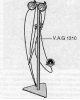
Check of tightness of the main brake cylinder
1. Unscrew the bleeder valve on one of the front brake calipers. 2. Connect and bleed the pressure gauge of the tester (V.A.G 1310) or (VAG 1310 A). 3. Load the brake pedal until the pressure gauge of the tester shows a...
1. Unscrew the bleeder valve on one of the front brake calipers. 2. Connect and bleed the pressure gauge of the tester (V.A.G 1310) or (VAG 1310 A). 3. Load the brake pedal until the pressure gauge of the tester shows a...

Removal and installation of the vacuum amplifier of brakes
Removing 1. Remove the decorative engine cover. 2. Remove the air filter assembly (see the relevant section in chapter Intake and exhaust system ). 3. Remove the battery and its support plate. 4. Using special equipment...
Removing 1. Remove the decorative engine cover. 2. Remove the air filter assembly (see the relevant section in chapter Intake and exhaust system ). 3. Remove the battery and its support plate. 4. Using special equipment...

Removal of air from the hydraulic brake system without the use of a device for filling the hydraulic brake drive and for removing air from it
1. Press the brake pedal again to increase the pressure in the brake system. 2. Insert the hose onto the bleed screw (cylinder bypass valve). 3. While depressing the brake pedal, loosen the vent screw and bleed the air...
1. Press the brake pedal again to increase the pressure in the brake system. 2. Insert the hose onto the bleed screw (cylinder bypass valve). 3. While depressing the brake pedal, loosen the vent screw and bleed the air...
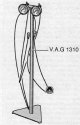
Checking, adjusting and setting values of the brake force regulator
The brake force regulator is attached to the rear axle support bracket and the regulator is controlled by the spring movement of the rear axle. Examination Firmly depress the brake pedal as far as it will go and quickly...
The brake force regulator is attached to the rear axle support bracket and the regulator is controlled by the spring movement of the rear axle. Examination Firmly depress the brake pedal as far as it will go and quickly...

Parking brake lever — appearance
1. Lever for engaging the parking brake system 2. Parking brake lever handle 3. Clamp 4. Adjusting nut 5. Bushing 6. Right guide tube 7. Left guide tube 8. Parking brake cable 9. Switch for parking brake indicator 10....
1. Lever for engaging the parking brake system 2. Parking brake lever handle 3. Clamp 4. Adjusting nut 5. Bushing 6. Right guide tube 7. Left guide tube 8. Parking brake cable 9. Switch for parking brake indicator 10....

Parking brake cable — removal and installation
1. Release the parking brake lever. 2. Remove storage shelf and armrest. 3. Loosen the adjusting nut (3), disconnect the cables (1) parking brake drive from the leveling clamp (2). 4. Remove the wheel. 5. Raise the car....
1. Release the parking brake lever. 2. Remove storage shelf and armrest. 3. Loosen the adjusting nut (3), disconnect the cables (1) parking brake drive from the leveling clamp (2). 4. Remove the wheel. 5. Raise the car....

Parking brake lever adjustment
Note. Thanks to the automatic adjustment of the clearance in the rear wheel brake mechanism, there is no need to adjust the hand lever for engaging the parking brake system during operation. A new adjustment should only...
Note. Thanks to the automatic adjustment of the clearance in the rear wheel brake mechanism, there is no need to adjust the hand lever for engaging the parking brake system during operation. A new adjustment should only...
Anti-lock braking system ABS — general information
Note. The ABS system belongs to the vehicle's safety systems; work on them requires detailed professional knowledge of the system. Inspection and replacement or repair work may only be carried out by a specially trained...
Note. The ABS system belongs to the vehicle's safety systems; work on them requires detailed professional knowledge of the system. Inspection and replacement or repair work may only be carried out by a specially trained...

The main electro-hydraulic module of the ABS system — removal and installation
Attention. Make sure that no brake fluid enters the hydraulic control connector. If the connector is dirty, clean it thoroughly with a jet of compressed air. Do not bend the brake lines near the hydraulic control unit....
Attention. Make sure that no brake fluid enters the hydraulic control connector. If the connector is dirty, clean it thoroughly with a jet of compressed air. Do not bend the brake lines near the hydraulic control unit....
This section is available on russian, bulgarian, belarusian, ukrainian, serbian, croatian, romanian, polish, slovak, hungarian
Read similar sections on other Skoda models
➧ Chassis (running gear): Brake system Skoda Fabia 1 (1999-2007)
➧ Chassis (running gear): Brake system Skoda Octavia 1 (1996-2004)
➧ Chassis (running gear): Brake system Skoda Superb 2 (2008-2015)
➧ Chassis (running gear): Brake system Skoda Felicia (1994-2001)
Link to this section in various formats
TEXTHTMLBB Code
- General information
- Faults en route
- User manual
- Maintenance and care
- Power unit
- Petrol engines
- Diesel engines
- Power and control system
- Lubrication system
- Cooling system
- Intake and exhaust system
- Transmission
- Clutch
- Mechanical gearbox
- Automatic gearbox
- Drive shafts
- Chassis (running gear)
- Front suspension
- Rear suspension
- Brake system
- Steering
- Body and interior
- Exterior (external elements)
- Interior (internal elements)
- Doors, locks and windows
- Heating and air conditioning
- Security systems
- Electrical equipment
- Equipment and devices
- Power devices
- Electrical circuits
- Electrical circuits (petrol)
- Electrical circuits (diesel)