
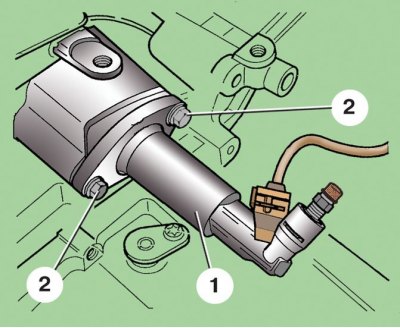
Throttle body
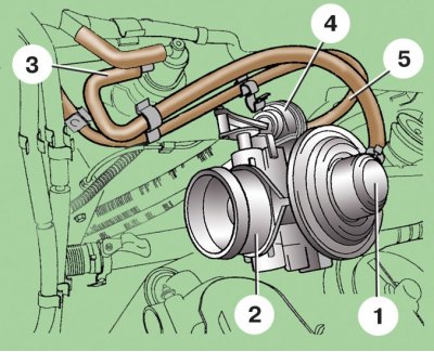
1 - exhaust gas recirculation valve; 2 - throttle body; 3 - hose; 4 - vacuum throttle actuator; 5 - vacuum hose
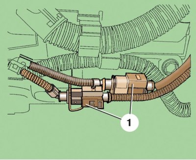
The engine control unit
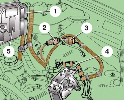
1, 2, 3 - connecting blocks; 4 – the holder of a plait of wires; 5 - engine control unit
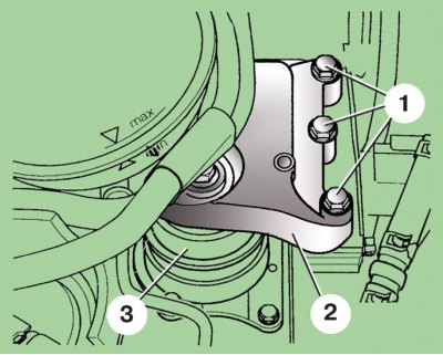
Bracket for shift rods
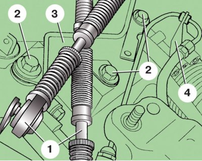
1 - gearshift rods; 2 – bolts of fastening of an arm; 3 - bracket; 4 - bracket on the gearbox
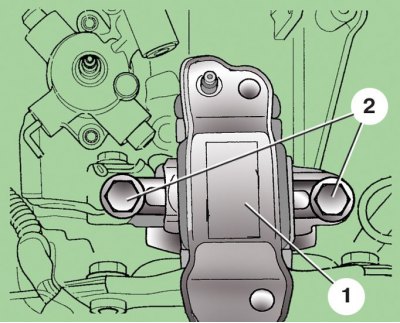
Gearshift rods
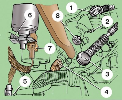
1 – a cable of a choice of transfers; 2 - lock washer; 3 – a cable of a gear change; 4 – connecting block of the switch of light of a backing; 5 - wire «masses»; 6 - wire; 7 - connecting block; 8 – a nut of fastening of the lever of a gear change
It is recommended to remove the engine assembled with the gearbox. To remove the engine, use a crane, hoist, winch, etc. load capacity 300 kg.
Attention! Hoses on the engine are fixed with three types of clamps: screw, spring and tape. Tape clamps are disposable; when installing the engine, they must be replaced with screw or spring clamps.
Attention! Fuel hoses may only be secured with spring clamps; screw and band clamps are not permitted.
Removal and installation of the engine are described on the example of a diesel engine, all other engines are removed and installed in the same way.
Removing
1. Remove the battery (see subsection 10.2).
2. Drain the liquid from the engine cooling system (see subsection 5.13).
3. Drain the oil from the crankcase (see subsection 3.6).
4. Remove the engine dust shield by unscrewing its fastening screws (see fig. Engine mud guard).
5. Remove the right wheel drive assembly (see subsection 7.1.3.7).
6. Turn away bolts of fastening and disconnect a drive of the left wheel from a semiaxis flange. Tie the drive to the body with wire so that it does not interfere.
7. Disconnect the muffler downpipe from the exhaust manifold (see subsection 6.2 and subsection 6.3).
8. Remove the front buffer.
9. Remove bolt 3 (see fig. Lower boost duct) fixing the lower air duct, remove the clamps 4 and then the air duct 1 with hose 2.
10. Remove rear support 2 (see fig. Rear support of the power unit) with bracket 3 by unscrewing bolts 1 and 4 securing it to the body and gearbox.
11. Remove the upper engine cover (see subsection 2.1).
12. Remove the air filter (see subsection 4.1).
13. Disconnect the alternator wires from the holder on the battery cover.
14. Disconnect the hoses from the radiator (see subsection 5.3).
15. For vehicles with air conditioning, disconnect the high and low pressure pipes and disconnect the high pressure pipe from the compressor. At the same time, please note that the air conditioning system can only be charged at a service station.
16. Remove the upper cross member of the front body (it has a hood latch).
17. Remove clamps 4 and air duct 6 with hose 8 (see fig. Engine compartment).
18. Remove the clamps 1 and disconnect the coolant supply hoses 5, supply 3 and fuel drain 2 from the tubes on the engine.
19. Disconnect the hose from the expansion tank 7 from below.
20. Disconnect the vacuum hose 5 (see fig. throttle body) from actuator 4 throttle.
21. Disconnect a hose 3 from the valve 1 recirculation of the fulfilled gases.
22. Slide the spring clamp and disconnect the hose 3 (see fig. heater hoses) from tee 4.
23. Move the spring clamp and disconnect the hose 2 from the branch pipe 1 of the heater radiator.
24. Disconnect hose 6 from vacuum pump 5.
25. Disconnect block 1 (see fig. The engine control unit) from the engine control unit 5.
26. Separate the pads 2 and 3 of the wiring harnesses and remove them from the holder.
27. Detach the holder 4 of the wiring harness from the mudguard.
28. Loosen three screws 2 (see fig. Bracket for shift rods) mounting bracket 3.
29. Take out from an arm 4 a tube of a drive of coupling.
30. Remove lock washer 2 (see fig. Gearshift rods), remove the selector lever and set it aside with cable 1. Remove the selector lever shaft bushings.
31. Unscrew the fastening nut 8, remove the gear lever and put it aside along with the cable 3.
32. Disconnect block 4 from the reverse light switch.
33. Disconnect «mass» spar wire.
34. Disconnect block 7 and a wire 6 from the traction relay of a starter.
35. Turn away two bolts 2 and take out from a case of a transmission the working cylinder 1 of a drive of deenergizing of coupling. Without disconnecting the hose from it, take the cylinder to the side.
Attention! When the slave cylinder is removed, do not press the clutch pedal.
36. Separate the pads 1 of the wiring harnesses and remove them from the holder under the starter.
37. Hook the engine on the eyelets and tighten the hoist cables.
38. Turn away three bolts 1 fastenings of the right support 3 of the power unit. If this lowers the engine, raise it with a hoist (2 - support bracket).
39. Turn away two bolts 2 fastenings of the left support 1 of the power unit.
40. Slightly lowering the power unit, carefully remove it from the engine compartment.
41. Place the power unit on a stand for dismantling or on a strong, stable support and remove the gearbox.
Installation
1. Replace all removed gaskets and O-rings with new ones.
2. Replace all self-locking nuts with new ones.
3. Before installing the exhaust pipe of the muffler, apply paste G 052 112 A3 to the exhaust manifold studs for threaded connections exposed to heat.
4. Insert the dropped gearbox centering sleeves.
5. Grease the gearbox input shaft splines.
6. Adjust the gearbox drive.
7. Fill with coolant and engine oil.
Tightening torques, Nm
| Thread: | |
| – M6 | 10 |
| – M7 | 15 |
| – M8 | 20 |
| – M10 | 40 |
| – M12 | 60 |
| Bolts for securing the gearbox housing to the engine block: | |
| – M10 | 45 |
| – M12 | 80 |
| Bolts of fastening of the right support of the power unit: | |
| - to the body | 20, then turn 90° |
| - to the engine | 30, then turn 90° |
| Bolts of fastening of the left support of the power unit: | |
| - to the body | 50, then turn 90° |
| - to the gearbox | 40, then tighten 90° |
| Bolts of fastening of a back support of the power unit: | |
| - to the gearbox | 30, then turn 90° |
| - to the body | 40, then tighten 90° |