



Electrical power devices of the vehicle Skoda Rapid 1

Starter — removal and installation
Removing 1. Loosen the fastening nut (1) and remove the wire «masses» from the body, as shown in the figure below. 2. Disconnect the wiring harness connector (2), as shown in the figure below. 3. Remove the plastic...
Removing 1. Loosen the fastening nut (1) and remove the wire «masses» from the body, as shown in the figure below. 2. Disconnect the wiring harness connector (2), as shown in the figure below. 3. Remove the plastic...

Checking the operation of the retracting and holding windings of the starter
Attention. To prevent burnout of the winding, this check should be carried out as soon as possible (no more than 10 s). 1. Disconnect the field winding wire from the terminal «M» traction relay. 2. Connect the positive...
Attention. To prevent burnout of the winding, this check should be carried out as soon as possible (no more than 10 s). 1. Disconnect the field winding wire from the terminal «M» traction relay. 2. Connect the positive...

Checking the starter when running without load
1. Clamp the starter in a soft grip vise and connect a fully charged 12V battery to the starter as follows: 2. Connect test ammeter (with a measurement limit up to 100 A) and carbon rheostat, as shown in the figure. 3....
1. Clamp the starter in a soft grip vise and connect a fully charged 12V battery to the starter as follows: 2. Connect test ammeter (with a measurement limit up to 100 A) and carbon rheostat, as shown in the figure. 3....

Checking the starter circuit
1. Remove from the relay and fuse box in the engine compartment, the fuel pump relay. 2. Set the shift lever to the position «N» or «R» (for automatic transmission) or press the clutch pedal (for manual transmission),...
1. Remove from the relay and fuse box in the engine compartment, the fuel pump relay. 2. Set the shift lever to the position «N» or «R» (for automatic transmission) or press the clutch pedal (for manual transmission),...

Checking starter cranking with a cold engine
1. Connect a voltmeter/ammeter to the battery terminals. 1. Conclusion (+) 2. Conclusion (-) 3. Mounting the induction ammeter 2. Apply the parking brake. Check that the gear lever is in position P. Start the engine. 3....
1. Connect a voltmeter/ammeter to the battery terminals. 1. Conclusion (+) 2. Conclusion (-) 3. Mounting the induction ammeter 2. Apply the parking brake. Check that the gear lever is in position P. Start the engine. 3....

Checking the technical condition (if the starter is ok)
Anchor check Attention. Depending on the year of manufacture and version, some of the values below may differ from those of your vehicle's instrumentation. 1. Remove starter assembly. 2. Disassemble the starter. 3....
Anchor check Attention. Depending on the year of manufacture and version, some of the values below may differ from those of your vehicle's instrumentation. 1. Remove starter assembly. 2. Disassemble the starter. 3....
Cleaning starter parts
1. Do not immerse parts in solvent. Submerging the yoke assembly or anchor will damage the insulator. Wipe these parts with a clean cloth. 2. Do not immerse drive components in cleaning solvent. A freewheel lubricated...
1. Do not immerse parts in solvent. Submerging the yoke assembly or anchor will damage the insulator. Wipe these parts with a clean cloth. 2. Do not immerse drive components in cleaning solvent. A freewheel lubricated...

Removal and installation of the alternator
Removing 1. Disconnect the wire connecting the battery terminal to ground (corps) car. 2. Remove poly V-belt. Vehicles with TDI engines with common rail injection system 3. Remove the top engine cover. 4. Remove the...
Removing 1. Disconnect the wire connecting the battery terminal to ground (corps) car. 2. Remove poly V-belt. Vehicles with TDI engines with common rail injection system 3. Remove the top engine cover. 4. Remove the...

Attaching the B+ wire to the alternator
Attention. The B+ wire screw connection on the alternator is labeled B1+1. If wire B- is not tightened to the specified tightening torques, the following danger occurs: The battery is not fully charged. Complete failure...
Attention. The B+ wire screw connection on the alternator is labeled B1+1. If wire B- is not tightened to the specified tightening torques, the following danger occurs: The battery is not fully charged. Complete failure...

Alternator carbon brush control
Length of new brushes = 12 mm Wear limit = 5 mm Mutual tolerance between brushes = +1 mm
Length of new brushes = 12 mm Wear limit = 5 mm Mutual tolerance between brushes = +1 mm

Removal and installation of the voltage regulator
Bosch voltage regulator 1. Unscrewing the lock nuts -arrows A- M6 - 12 Nm, M8 - 30 Nm), unscrew the cover fixing screw -arrow B- (3 Nm). 2. Remove the cover. 3. Remove the fixing screws -arrows- (2 Nm) voltage...
Bosch voltage regulator 1. Unscrewing the lock nuts -arrows A- M6 - 12 Nm, M8 - 30 Nm), unscrew the cover fixing screw -arrow B- (3 Nm). 2. Remove the cover. 3. Remove the fixing screws -arrows- (2 Nm) voltage...
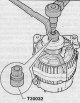
Removal and installation of a pulley of a V-ribbed belt of the alternator
Note. Necessary devices, special control and measuring devices, as well as auxiliary means: Socket wrench -T30032-. 1. Remove the V-ribbed belt and, if necessary, the alternator. 2. Using a socket wrench (Т30032) remove...
Note. Necessary devices, special control and measuring devices, as well as auxiliary means: Socket wrench -T30032-. 1. Remove the V-ribbed belt and, if necessary, the alternator. 2. Using a socket wrench (Т30032) remove...

Checking the technical condition of the charging system
Attention. Check that the battery wires are connected to the terminals. Never disconnect the wires from the battery while the engine is running. Attention. Depending on the year of manufacture, different readings are...
Attention. Check that the battery wires are connected to the terminals. Never disconnect the wires from the battery while the engine is running. Attention. Depending on the year of manufacture, different readings are...

Checking the technical condition of the generator (if understood)
Rotor check 1. Check the rotor winding for damage. Check the resistance between the generator rings. If the resistance is low, then there is a short circuit in the rotor (short circuit). If there is no connection, then...
Rotor check 1. Check the rotor winding for damage. Check the resistance between the generator rings. If the resistance is low, then there is a short circuit in the rotor (short circuit). If there is no connection, then...


Disconnecting and connecting the battery
Detachment Note. Before proceeding to disconnect the battery, you should find out the car radio and navigation code, respectively. This does not apply to radios and navigations installed by the manufacturer. 1. After...
Detachment Note. Before proceeding to disconnect the battery, you should find out the car radio and navigation code, respectively. This does not apply to radios and navigations installed by the manufacturer. 1. After...
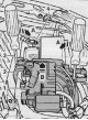
Removing and installing the battery
Removing 1. Disconnect the negative terminal from the battery (4), shown in the figure below. 2. Holding the lid open (3), unscrew the nut securing the positive terminal (2) battery as shown in the figure below. 3....
Removing 1. Disconnect the negative terminal from the battery (4), shown in the figure below. 2. Holding the lid open (3), unscrew the nut securing the positive terminal (2) battery as shown in the figure below. 3....

Removing and installing the battery holder
Removing 1. Remove the battery assembly (see relevant section in this chapter). 2. On vehicles with a Start-Stop system - disconnect from the latches (2) and remove the cover (1), shown in the figure below. On vehicles...
Removing 1. Remove the battery assembly (see relevant section in this chapter). 2. On vehicles with a Start-Stop system - disconnect from the latches (2) and remove the cover (1), shown in the figure below. On vehicles...
Warning instructions and safety rules for working with batteries
Attention. Persons under supervision, such as apprentices or trainees may only work on car batteries under the supervision of professional personnel, such as mechanic / foreman or electrician / foreman. The acid is...
Attention. Persons under supervision, such as apprentices or trainees may only work on car batteries under the supervision of professional personnel, such as mechanic / foreman or electrician / foreman. The acid is...
Visual control of the battery
Attention. There is a risk of injury when handling batteries. Observe the warning and safety instructions. If the battery is not professionally fixed, it may be damaged. Perform fastening control. Before proceeding with...
Attention. There is a risk of injury when handling batteries. Observe the warning and safety instructions. If the battery is not professionally fixed, it may be damaged. Perform fastening control. Before proceeding with...
Battery voltage measurement
Open circuit voltage Note. Necessary special devices, control and measuring devices, as well as auxiliary means: Hand multimeter (e.g. -VAG 1526A -). Note. The battery must not be loaded with electrical consumers at...
Open circuit voltage Note. Necessary special devices, control and measuring devices, as well as auxiliary means: Hand multimeter (e.g. -VAG 1526A -). Note. The battery must not be loaded with electrical consumers at...
Current take-off control during battery charging
In order to obtain, as early as possible, information about the condition of discharged batteries, it is possible, by the amount of current consumed by the battery at the beginning of charging, to assess whether it is...
In order to obtain, as early as possible, information about the condition of discharged batteries, it is possible, by the amount of current consumed by the battery at the beginning of charging, to assess whether it is...
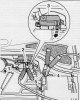
Charging the battery
Attention. Batteries with a colorless or light yellow eye should not be monitored or charged. These batteries need to be replaced. During battery charging, voltage measurement and measurement with current load, the...
Attention. Batteries with a colorless or light yellow eye should not be monitored or charged. These batteries need to be replaced. During battery charging, voltage measurement and measurement with current load, the...
Deeply discharged batteries
Batteries that have not been used for a relatively long time, such as stored vehicles, will self-discharge. The battery is deeply discharged when its open circuit voltage drops below 11.6 V. Measure the open circuit...
Batteries that have not been used for a relatively long time, such as stored vehicles, will self-discharge. The battery is deeply discharged when its open circuit voltage drops below 11.6 V. Measure the open circuit...
This section is available on russian, bulgarian, belarusian, ukrainian, serbian, croatian, romanian, polish, slovak, hungarian
Read similar sections on other Skoda models
➧ Electrical equipment: Power devices Skoda Favorite (1987-1994)
Link to this section in various formats
TEXTHTMLBB Code
- General information
- Faults en route
- User manual
- Maintenance and care
- Power unit
- Petrol engines
- Diesel engines
- Power and control system
- Lubrication system
- Cooling system
- Intake and exhaust system
- Transmission
- Clutch
- Mechanical gearbox
- Automatic gearbox
- Drive shafts
- Chassis (running gear)
- Front suspension
- Rear suspension
- Brake system
- Steering
- Body and interior
- Exterior (external elements)
- Interior (internal elements)
- Doors, locks and windows
- Heating and air conditioning
- Security systems
- Electrical equipment
- Equipment and devices
- Power devices
- Electrical circuits
- Electrical circuits (petrol)
- Electrical circuits (diesel)