
2. Remove the upper trim of the A-pillars (see Section 17).
3. Using a plastic wedge, remove the top trim (1 per resist. illustrations) steering column.

15.3 Steering column top trim
4. Remove the screws (1 and 3 on resist. illustrations) and remove the lower steering column cover (2).
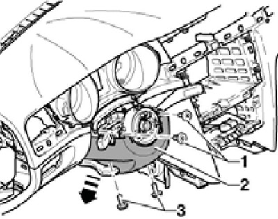
15.4 Steering column bottom trim
Note: When installing, tighten the screws to 1.5 Nm.
5. Remove the damping panel under the instrument panel (see resist. illustration).
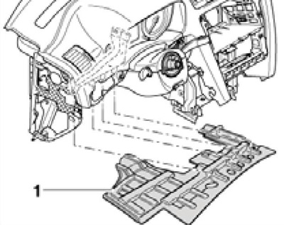
15.5 Damping panel
6. Pry off the decorative strips with a plastic wedge (1-3) and take them off. Remove deflectors (4 and 5), as described in Chapter 3.
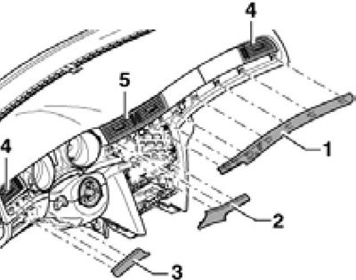
15.6 Decorative strips and deflectors
7. Remove the instrument cluster (1 per resist. illustrations), as described in Chapter 12, and a flashing (3) steering column. Disconnect the park assist buzzer connector (behind the instrument cluster).
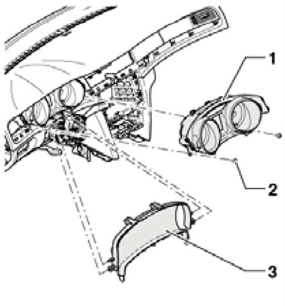
15.7 Removing the instrument cluster
8. Remove paddle shifters (see chapter 12). If present, disconnect the multifunction switch connector.
9. Remove the pads (1 and 2 on resist. illustrations) audio unit and climate control panel. Disconnect the front passenger airbag warning light connector. Remove the screws (3), pull out the climate system panel (4) and disconnect its connectors. Remove the audio block (see chapter 12).
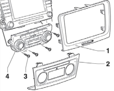
15.9 Overlays of the audio block and the panel of the climatic system
10. Remove the end cap (1 per resist. illustrations) instrument panel, prying it with a screwdriver in the area (2). Remove the screws securing the fuse mounting block.
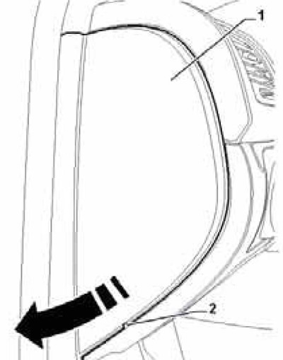
15.10 Left instrument panel trim
11. Remove the overlay of the outdoor lighting control switch, disconnect the connector of its electrical wiring, as well as the connectors for the headlight tilt and brightness controls.
12. Remove the switch of the alarm system and the sensor of intensity of solar radiation.
13. Unlock the latch (3 on resist. illustrations) and unhook the handle (1) glove box (2). Screw (4) glove box cannot be turned out without removing the glove box.
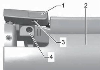
15.13 Removing the glove box handle
14. Pull the front passenger airbag switch out of the glove box and disconnect the switch connector. Remove the screws (2 to resist. illustrations) glove box mounts (1) and disconnect its backlight connector. Disconnect the connector for lighting the front right foot well, disconnect the air duct from the glove box and remove the box.
Note: When installing, tighten the screws to 1.5 Nm.
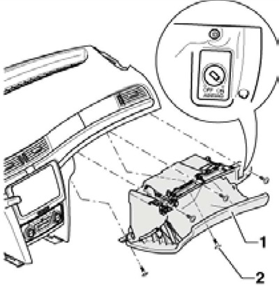
15.14 Removing the main storage box
15. Remove the screws (1 per resist. illustrations) driver's glove box (2) and take it off. Disconnect the diagnostic connector, driver's footwell light, right frontal airbag, and footwell temperature sensors.
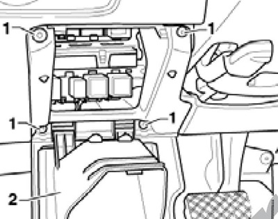
15.15 Fixing the driver's glove box
Note: When installing, tighten the screws to 1.5 Nm.
16. Remove the screws (2 to resist. illustrations). Push the instrument panel towards the windshield to loosen the metal safety hooks (3) and unhook these hooks by pushing them with a short screwdriver in the direction of the arrows (A) turn of openings for deflectors. Pull out the instrument panel in the direction of the dotted arrows.
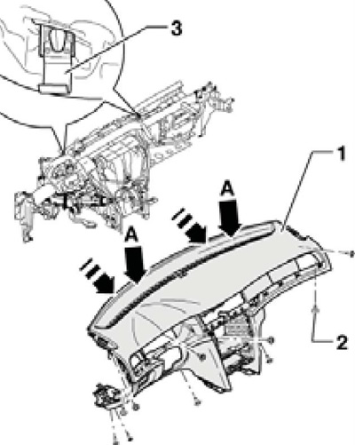
15.16 Removing the instrument panel
Note: When installing, tighten the screws to 2 Nm.
17. Make sure that the wiring connectors of the instrument panel parts are disconnected and carefully remove the instrument panel.
18. Installation is carried out in the reverse order. When installing the lower trim of the steering column, make sure that the correct distance between the trim and the steering wheel is maintained. If after installing K / L SRS indicates a malfunction, clear the fault memory.