



Note: The nameplate with the additional heater data is located on the heater itself and is also duplicated on the front panel of the engine compartment.
1. The location of the main parts of the additional heater are shown in the accompanying illustrations.
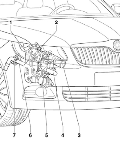
16.1a Location of the main components of the additional heater
1 Additional heater with control unit "J364"
2 Fuel line with quick release coupling
3 Air intake
4 Exhaust system
5 Coolant circulation pump "V55"
6 Rear exhaust pipe
7 Protection
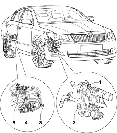
16.1b Fuel supply details for additional heater
1, 3 Quick release coupling
2 Additional heater
4 Dosing pump "V54"
5 Fuel supply module, in the fuel tank
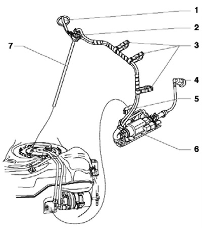
16.1c Dosing pump installation details
1 Gasket on the fuel tank
2 Connector of the dosing pump "V54"
3 Wiring Holders
4 Quick release coupling
5 Bracket for dosing pump "V54"
6 Dosing pump "V54"
7 Fuel pipe
2. To remove the air intake, remove the front bumper trim (see Chapter 11), unscrew the bolt (1 on the accompanying illustration) and remove the air intake (B) from the intake pipe.
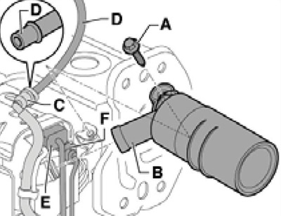
16.2 Removing the air intake
3. To remove the coolant circulation pump "V55", loosen the clamps (1 on the accompanying illustration), disconnect the coolant hoses from the pump, disconnect the pump connectors and unscrew the bolt (2). After installation, fill the engine cooling system (see section 2).
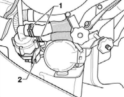
16.3 Removing the coolant circulation pump "V55"
4. To remove the exhaust system, loosen the clamp (1 on the accompanying illustration) and unscrew the bolts (2 and 3). When installing, tighten the bolts and clamp with a force of 7 Nm.
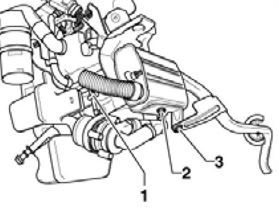
16.4 Removing the exhaust system
Removal and installation, disassembly and assembly of an additional heater
Note: If the additional heater needs to be replaced, first connect the VAS5051 diagnostic tool and start the function "Replace control unit".
5. Disconnect the negative cable from the battery.
6. Remove the right front wheel arch liner and the front bumper trim (see Chapter 11).
7. Remove the washer fluid reservoir (see Chapter 12).
8. Clamp the coolant hoses (1 and 2 in the accompanying illustration) and disconnect them from the auxiliary heater.
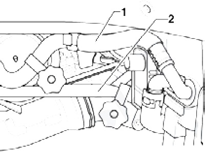
16.8 Coolant hoses on additional heater
9. Disconnect the fuel line from the auxiliary heater and disconnect the electrical wiring connectors.
10. Unscrew the bolt (1 on the accompanying illustration) and give the nut (2).
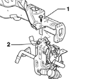
16.10 Additional heater fastening (8 Nm)
11. Loosen the clamp (3 on the accompanying illustration), loosen the nut (1) and remove the additional heater (2).
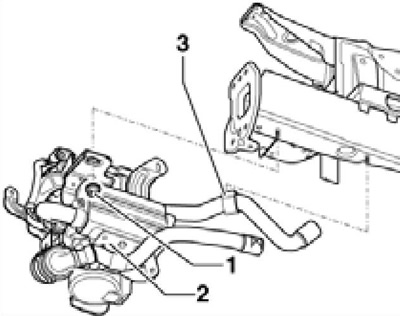
16.11 Removing the additional heater
12. If it is necessary to disassemble the housing, follow the accompanying illustration. On diesel models, a non-removable heating element "Z66" is installed in the combustion chamber. Its wires are connected to the leads of the glow plug "Q8". In this version, if the glow plug fails, the combustion chamber assembly must be replaced.
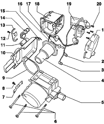
16.12 Additional heater assembly parts
1 Cover of the additional heater control unit J364
2 Temperature sensor G18
3 Sensor 189 overheating
4 Combustion chamber
5 Heat exchanger
6 Bolts, 7 Nm
7 Retaining spring
8, 12, 20 Bolts, 4 Nm
9 Gasket, subject to replacement
10 Lid
11, 14 Connections to the coolant circuit
13, 15 Retainer
16 Glow plug "Q8" with ignition sensor
17 Firestarter
18 Additional heater housing
19 Additional heater control unit J364
13. Installation is carried out in the reverse order. Nut (1 in illustration 16.11) tighten to 15 Nm. After installation, bleed the engine cooling system. If the previous heater is installed, connect the VAS5051B diagnostic tool and run the function "Unlock heater unit".