



Heater radiator
1. Set the climate control system to maximum temperature, turn off the ignition and all electrical appliances.
2. Clamp the coolant hoses (1 on the accompanying illustration) heater radiator, mark them, pull out the clamps and disconnect the hoses from the radiator, collecting the leaking coolant. If the radiator is supposed to be replaced, the coolant should also be replaced, so in this case it can be drained (see Section 2).
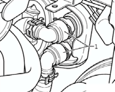
13.2 Coolant hoses on the heater radiator
3. Connect the compressor to the upper fitting of the heater radiator (1 on the accompanying illustration) and blow out the remaining coolant from the radiator (3) into a previously prepared container (2).
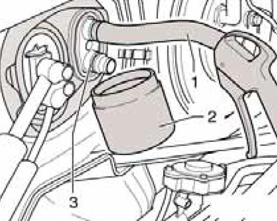
13.3 Removing residual coolant from the radiator
4. Loosen the bolt (1 on the accompanying illustration) on the flange of the heater radiator between the fittings. This loosens the coolant pipe, making it easier to remove the radiator.
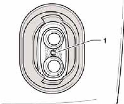
13.4 Bolt on connecting flange
5. Remove the left side cover of the center console (see Chapter 11), air duct to the left footwell (see Section 10) and knee airbag (if available, see Chapter 12).
6. Remove the screws (1 on the accompanying illustration) and remove the radiator cover.
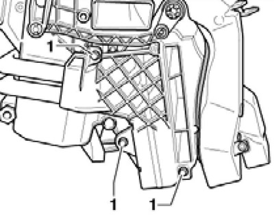
13.6 Removing the cover
7. Cover the flooring under the heater core with waterproof material and absorbent paper. Open the clamps (1 on the accompanying illustration), pull the tubes out of the radiator and remove it from the air conditioning system housing.

13.7 Connecting the coolant pipes on the radiator
8. Wet the new O-rings (2 on the accompanying illustration) coolant and insert them into the connections (3) of the radiator, then press the coolant tubes (1) into them.
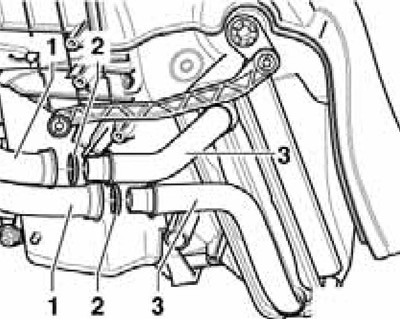
13.8 Radiator seals
9. Secure the tubes with clamps as shown in Illustration 13.7, applying a force of 1.5 Nm.
10. Further installation is carried out in the reverse order. Finally, check and, if necessary, adjust the coolant level.
Auxiliary heating element "Z35"
11. Remove the left side cover of the center console (see Chapter 11) and the air duct to the left footwell (see Section 10).
12. If the lever is located opposite the left temperature flap so that access to the upper bolt (And on the accompanying illustration) closed by lever (C), change the temperature setting on the climate control panel. Disconnect the negative cable from the battery, unscrew the bolts (A) and remove the cover (B).
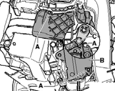
13.12 Providing access to the heating element Z35
13. Give the nut (And on the accompanying illustration) ground connections, disconnect the connector (B) from the strip (2) and pull the heating element "Z35" (C) out of the climate control system housing.
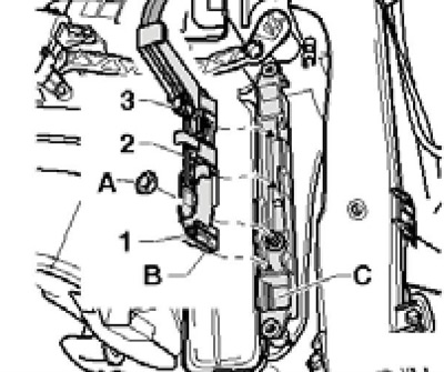
13.13 Removing the heating element Z35
14. Installation is carried out in the reverse order. Tighten the nut with a force of 9 Nm.