



Contents: Activator "V113" of the circulation…⬇ Activator "V425" of distribution and…⬇ Activator "V68" of the temperature…⬇ Activator "V145" (system "Climatic")…⬇ Activator "V159" of the right…⬇ Activator "V107" of the glass…⬇
Activator "V113" of the circulation flap (system "Climatic")
1. Remove the main storage compartment (see Chapter 11).
2. Remove the cover (1 on the accompanying illustration) activator "V113" (2), disconnect its connector and pull out the activator.
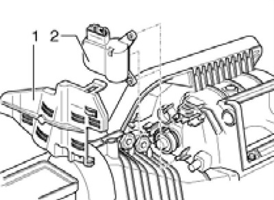
12.2 Removing the V113 activator
3. Installation is performed in reverse order. After installation, check the operation of the activator.
Activator "V425" of distribution and circulation valves (climatronic system)
4. Remove the main storage compartment (see Chapter 11). On models with keyless entry system, remove its control unit "J518".
5. Remove the bolts (1 on the accompanying illustration), turn the "V425" activator (2) at an angle of 15° in the direction of the arrow, pull it out of the bushing and remove it towards you. Disconnect the electrical wiring connector.
Note: After removal, do not change the position of the circulation flap.
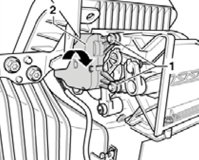
12.5 Removing the V425 activator
6. Installation is carried out in the reverse order. The activator is installed on the polyhedral axis in only one position (see accompanying illustration). After installation, check the operation of the activator and perform the function "Initiate basic setting" using a diagnostic device.
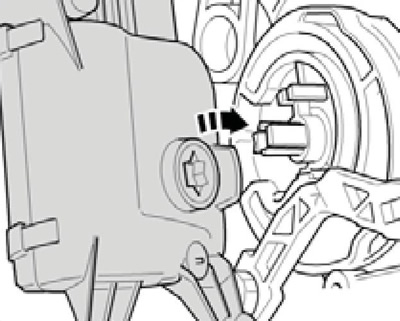
12.6 Installing the V425 activator
Activator "V68" of the temperature flap (system "Climatic") and activator "V158" of the left temperature flap (system "Climatronic")
(Material published on the website: SKODABOOK.RU)
7. Remove the air duct to the left footwell (see Section 10).
8. Remove the diagnostic interface J533 from the bracket in the steering column area (see Chapter 12).
9. Remove the bolts (3 on the accompanying illustration).
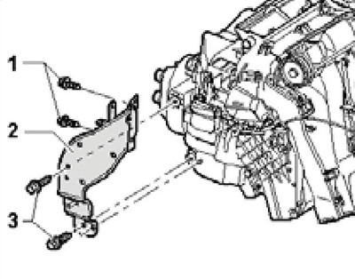
12.9 Bracket fastening
Note: Do not loosen the bolts (1) or remove the bracket (2).
10. Press on the bracket (1 on the accompanying illustration) in the direction of the brake pedal (arrow) and hold it in this position. You can secure the bracket with a clamp.
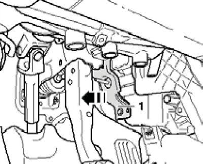
12.10 Bracket offset
11. Label the connector plug (With accompanying illustrations) activator to avoid accidentally connecting it to another socket, and disconnect the connector. Remove the cover (A), unscrew the bolts (D), remove the activator "V68", "V158" (B) and disconnect its lever (E) from the rod (F).
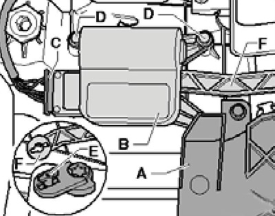
12.11 Removing the V68/V158 activator
12. Installation is carried out in the reverse order. Bolts (D in illustration 12.11) tighten with a force of 1.4 Nm. After installation, check the operation of the activator and perform the function "Initiate basic setting" using a diagnostic device.
Activator "V145" (system "Climatic") or "V426" (system "Climatronic") front distribution valve
13. Remove the instrument cluster (see Chapter 11).
14. Disconnect the connector of the activator "V426", unscrew the bolts (1 on the accompanying illustration) and remove the activator.
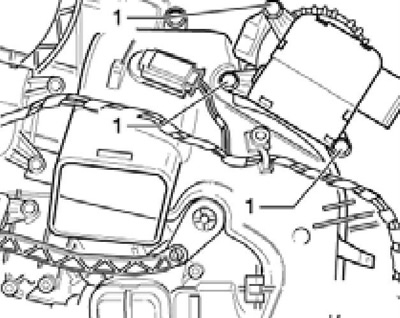
12.14 Fastening of the activator V426 (V147)
15. Installation is carried out in the reverse order. After installation, check the operation of the activator and perform the function "Initiate basic setting" using a diagnostic device.
Activator "V159" of the right temperature flap (system "Climatronic")
16. Remove the main storage compartment (see Chapter 11).
17. Remove the bolts (1 on the accompanying illustration), remove the activator, disconnect its connector and unhook the support (2) from it.
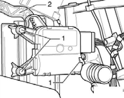
12.17 Removing the V159 activator
18. Installation is carried out in the reverse order. After installation, check the operation of the activator and perform the function "Initiate basic setting" using a diagnostic device.
Activator "V107" of the glass blowing flap (system "Climatronic")
19. Remove the instrument panel (see Chapter 11).
20. Remove the air duct to the left footwell (see Section 10).
21. Remove the diagnostic interface J533 (see Chapter 12).
22. Remove the bolts (1 and 3 in Illustration 12.9) and remove the bracket (2).
23. Label the connector plug (With accompanying illustrations) activator to avoid accidentally connecting it to another socket, and disconnect the connector. Unscrew the bolts (A), remove the "V107" activator (B) and disconnect its lever (E) from the rod (D).
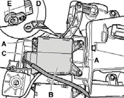
12.23 Removing the V107 activator
24. Installation is carried out in the reverse order. Bolts (1 in illustration 12.9) tighten with a force of 10 Nm. After installation, check the operation of the activator and perform the function "Initiate basic setting" using a diagnostic device.