



Note: G191/G192 sensors are not installed on models from week 46 of 2010.
1. To remove the "G263" evaporator outlet temperature sensor, remove the right side trim of the center console, disconnect the connector (1 on the accompanying illustration) sensor, turn it in the direction of the arrow at an angle of 90° and pull it out of the climate control system housing.
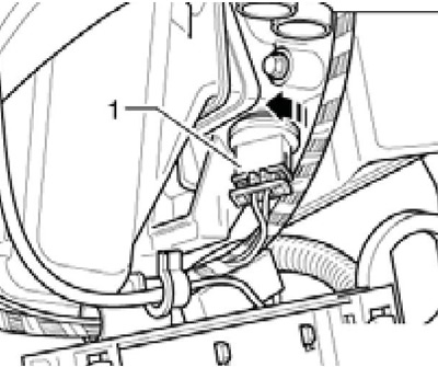
14.1 Sensor G263
2. To remove the "G192" sensor for the temperature of the air supplied to the foot wells (on models with the "Climatic" system), remove the air duct to the left foot well (see Section 10), turn the sensor (2 in illustration 14.2a) in the direction of the arrow at an angle of 90°, pull it out of the climate control system housing and disconnect the sensor connector (1). On models with the system "Climatronic" in place of the sensor "G192" the sensor "G261" of the temperature of the air supplied to the left foot well is installed, and the sensor "G262" of the temperature of the air supplied to the right foot well is installed on the right side (see illustration 14.2b) and is accessible after removing the main glove compartment. The "G262" sensor is removed in the same way. When installing the G192/G261/G262 sensors, pay attention to the correct position of the sealing ring (3).
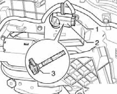
14.2a Sensor G192/G261
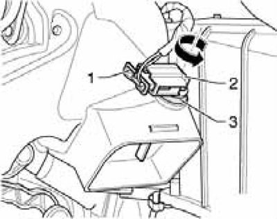
14.2b Sensor G262
3. To remove the sensor "G191" (2 on the accompanying illustration) temperature of the air supplied from the central deflectors (on models with the "Climatic" system), the driver's glove compartment (see Chapter 11), turn the sensor (2 on the accompanying illustration) at an angle of 90°, pull it out of the climate control system housing and disconnect the sensor connector (1). On models with the system "Climatronic" sensors "G150" and "G151" of the temperature of the air supplied through the left and right central deflectors, respectively, are removed in the same way after removing the corresponding glove compartment (see Chapter 11). When installing the G192/G261/G262 sensors, make sure that the sealing ring (3) is correctly positioned.
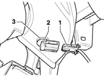
14.3 Sensor G191/G150/G151
4. To remove the sensor "G107" or sensor No.2 "G134" solar radiation (1 on the accompanying illustration) press it out of the instrument panel (3) using plastic wedge No.3409 and disconnect the connector (2).
View the original on the website (www.SKODABOOK.ru)
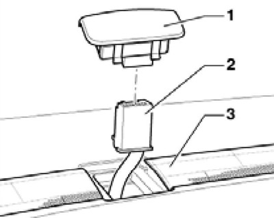
14.4 Sensor G107/C134
5. To remove the sensor "G238" (3 on the accompanying illustration) air quality, remove the right windshield fairing cover (see Chapter 11), disconnect the connector (1 on the accompanying illustration) sensor "G238", press the lock (2), turn the sensor at an angle of 90° and remove it. After removal, keep the sensor clean, do not allow the sensor to come into contact with liquid chemicals (solvents, fuels, etc.) or their vapors.
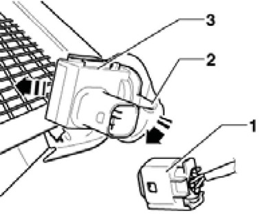
14.5 Removing the G238 sensor