
Fuel system diagram
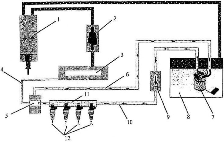
1 - a tank with activated carbon; 2 - solenoid valve of the tank with activated carbon; 3 - suction pipeline; 4 - low pressure pipeline; 5 - pressure regulator; 6 - bypass fuel line; 7 - fuel pump; 8 – fuel tank; 9 - fuel filter; 10 - fuel supply line; 11 - fuel distributor; 12 - nozzles
Engine 1.6-55 kW (AEE) Equipped with electronically controlled multipoint fuel injection (MPI) 1 A.V. This system is self-learning control program. The intake air quantity is calculated from the air pressure and temperature in the intake manifold and the engine speed. The amount of fuel is set depending on the required mixing ratio. Sensors (sensors) systems allow you to adjust the initial adjustment in accordance with the operating conditions of the engine.
The signal about the moment of ignition of the mixture and the engine speed enters the system from the Hall sensor located on the ignition distributor. The distributor is directly connected to the camshaft. While the engine control unit (further UU) will not receive a signal from the Hall sensor, you can not start the engine.
The CU system determines the top dead center of the first cylinder by a static evaluation of the four holes from which signals are sent to the sensor. One hole is wider than the other three. From this moment, the sequential distribution of the injection in the order of the cylinders begins and, similarly, the ignition. It also provides for selective adjustment of the ignition timing, which protects against detonation combustion (and thus from knocking in the engine).