



Note: Checking the condition and replacing the windshield wiper blades, as well as adjusting the washer fluid supply nozzles and the parking position of the wipers are described in Section 7 Chapter 1. A description of the removal and installation of the steering column switches is given in Section 9.
Levers
1. Remove the caps, give away the nuts (see illustration) and remove the levers.
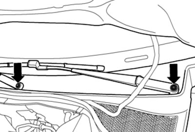
10.1. Lever mounting nuts
2. If necessary, use the T10369/1 puller to remove the levers (see illustration).
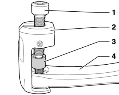
10.2. Puller T10369/1 lever (4)
3. Installation is carried out in reverse order. Adjust the parking position of the levers (see Section 7 Chapter 1). Tighten the nuts to 20 Nm.
Mechanism
4. Remove the windshield wiper arms (see subsection above).
Information taken from this resource (SKODABOOK)
5. Remove the windshield fairing (see Chapter 11).
6. Disconnect the connector (2 in the illustration) electric motor, move the wiring (3) to the side, unscrew the bolts (1 and 4) and remove the windshield wiper mechanism.
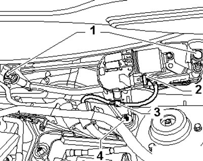
10.6. Fastening the windshield wiper mechanism
7. Installation is carried out in reverse order. Bolts (1 in illustration 10.6) tighten the bolts to 10 and 5 Nm respectively.
Electric motor
8. Remove the windshield wiper mechanism (see subsection above).
9. Pry and separate the rod (1 in the illustration) from the crankshaft joint head of the electric motor (arrow). For this purpose, you can use the MP8-602/1 device.
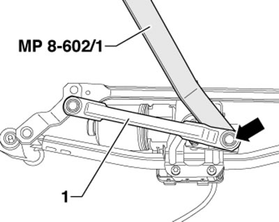
10.9. Separation of thrust from electric motor
10. Give the nut (1 in the illustration) and separate the crank (2) from the electric motor shaft. Then unscrew the bolts (arrows), remove the carrier plate (3) and remove the electric motor with the control unit from the windshield wiper mechanism.
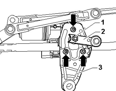
10.10. Fastening the electric motor of windshield wipers
11. Connect the electric motor wiring connector and turn it on to set it to the lower parking position. Insert the electric motor with the control unit onto the windshield wiper mechanism so that it fits into the cutouts in the rod (see illustration).
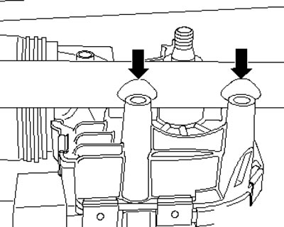
10.11. Cutouts in the traction
12. Install the carrier plate (3 in illustration 10.10) and tighten its bolts (arrows) with a force of 9 Nm. Position the crank (2 on the accompanying illustration) on the electric motor so that the distance (a) between the edge of the crank and the edge of the carrier plate (3) is 2.7 mm. Tighten the nut (1) with a force of 18 Nm.
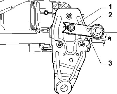
10.12. Installation position
13. Press the rod onto the pivot head.