



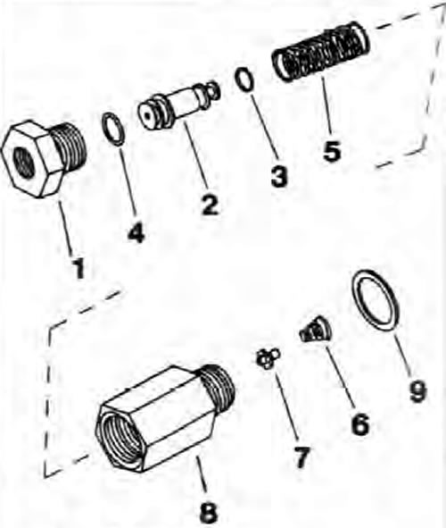
Fig. 9.8. Components of the brake pressure regulating valve (except Pickup models)
1. End cap; 2. Piston; 3. Small O-ring; 4. Large O-ring; 5. Piston spring; 6. Valve spring; 7. Plastic valve; 8. Valve body; 9. O-ring seal.
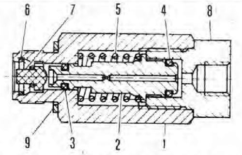
Fig. 9.9. Sectional view of the brake system pressure control valve (except Pickup models)
1. Valve body; 2. Piston; 3. Small O-ring; 4. Large O-ring; 5. Piston spring; 6. Valve spring; 7. Plastic valve; 8. End cap; 9. O-ring seal.
Note: Before you begin, please refer to the Note given at the beginning Chapters 9.
Note: If one or both rear wheels lock up several times under heavy braking, first check that this is not caused by adverse road conditions or incorrect tire pressure/excessive tread wear. Then check the condition of all four brake assemblies. Only then can we assume that the brake pressure regulating valve is faulty. Note that the rear valve services the primary circuit, which includes the left rear brake, while the front valve services the secondary circuit, and therefore the right rear brake - this will help to conclude which of the valves is faulty.
Note: Valves fitted to the Hatchback model are marked with the number 003 stamped on the valve body; valves of the Station Wagon and Van models are marked with the number 004 (or 400, dark colored end cap). Make sure both valves are marked the same, matching model, and if one of the valves needs to be replaced, purchase a new component of the correct type.
Removal
1. Minimize fluid loss. To do this, remove the master cylinder feed tank cap and tighten it again, placing a piece of polyethylene under the cap (do not damage the level sensor). This will create a tight seal and prevent fluid from spilling. Alternatively, plug the metal brake pipe immediately after separating it from the valve (see Chapter 10). In addition, it is necessary to seal the valve and master cylinder holes; work very carefully to prevent foreign particles from entering the system.
2. Loosen the union nut and separate the metal brake pipe. Try to minimize fluid loss and clean any spilled fluid from adjacent components as soon as possible.
3. Unscrew the valve and remove it from the master cylinder; remove and discard the O-ring.
Bulkhead
Note: Before you start overhauling the valve, check for the availability of the necessary components and their foam, compare them with the price of a new or repaired valve in the workshop, and only then decide whether overhaul is advisable. In addition, read the description of the procedure to the end and prepare all the required tools and devices.
4. Remove the valve from the engine compartment and clean it thoroughly.
5. Carefully clamp the valve body in a vice with soft-grip jaws and unscrew the end cap.
6. Keeping in mind the order of removal and orientation of each component, remove the piston assembly with spring and O-rings by lightly tapping the valve body against a clean wooden surface. If necessary, clamp the valve body in a vice with soft jaws and apply low-pressure compressed air to the valve bore to facilitate removal of the piston assembly.
Warning: Be careful, the piston may pop out with some acceleration.
7. Clean all components thoroughly using only methyl or isopropyl alcohol, or clean brake fluid. Never use mineral solvents such as gasoline or kerosene for this purpose - they will damage the rubber components of the brake hydraulic system. Dry the components using compressed air or a clean, dense (lint-free) cloth.
8. Inspect all components and replace any that are worn or damaged. Pay particular attention to the inside walls of the valve body and the pistons - the complete valve assembly should be replaced if they are scratched, worn or corroded. If there is any doubt about the condition of the assembly or any of its components, replace accordingly.
9. If the assembly is suitable for further use, purchase the components necessary to reassemble it. Be sure to replace all O-rings - they should never be reused.
10. When assembling, soak the pistons and new seals with clean brake fluid. Apply clean fluid to the walls of the valve body, then insert the valve and its spring.
11. Install new O-rings into the piston grooves without using any tools (otherwise the seals may be damaged). Install the spring onto the piston and insert the assembly into the valve body, ensuring that all components are installed in the correct order and orientation.
12. Install the end cap, making sure it is correctly aligned with the piston, tighten the cap to the specified tightening torque Specifications.
13. Install the valve into the master cylinder.
Installation
14. Install in the reverse order of removal, paying attention to the following:
- a) Be sure to replace the O-ring.
- b) Tighten the valve with the specified tightening force Specifications.
- c) Fill the reservoir with new fluid and bleed the appropriate part of the system (see Chapter 9). Check the system joints for leaks.