



Contents: Ignition system ⬇ Preheat system ⬇ Engine management system, data…⬇ Safety precautions when working with…⬇
Ignition system
The ignition system ensures the ignition of the air-fuel mixture supplied to the combustion chambers of the cylinders of gasoline engines. To generate a spark of the required intensity, the 12-volt voltage of the on-board network on 1.4 and 1.8 l engines is converted into high-voltage voltage in the ignition coils installed above each spark plug (high voltage wires are not used). On 1.2L engines, the on-board voltage is converted to high voltage in the ignition module, from which it is transmitted via high-voltage wires to each spark plug. The electronic ignition system is an integral part of the engine management system. Its main working components are spark plugs and coils. The supply of high voltage to the spark plugs is controlled by the engine electronic control module (ECM). Manual adjustment of the ignition timing is not performed - if the required settings are violated, the failed components must be replaced. The ignition system components are not subject to wear and tear and do not require regular maintenance. In accordance with the maintenance schedule, only the spark plugs should be replaced (see Section 14 Chapter 1).
Preheat system
When a diesel engine is running, clean air is sucked into its cylinders and compressed to high pressure. In this case, the air temperature rises above the ignition temperature of diesel fuel. The fuel is injected into the cylinder with some advance and self-ignites. Thus, spark plugs are not used to ignite the fuel in a diesel engine. On a cold engine, the compressed air temperature may not reach the value required for ignition. In this case, additional preheating is required.
For this purpose, a glow plug is installed in each cylinder, heating the combustion chamber. The operation of the glow plugs is controlled by the ECM based on signals from the ECT and SKR sensors.
Engine management system, data transmission buses
Basic information on the operation and sensors of the engine management and fuel injection systems is presented in Chapter 4.
The control units are connected to each other via CAN and LIN data buses. Networking makes it possible to exchange data between individual control units in a way that is not conventional (discrete) cable connections, and via data buses in digital form as an electrical signal. Due to this, data transmission is carried out to a larger number of control units.
The CAN bus is divided into five separate main subsystems: CAN-P (drive), CAN-C (comfort), CAN-I (information systems), CAN-D (diagnostics) and CAN instrument cluster. These subsystems are connected to each other via the diagnostic interface "J533", built into the "J520" unit (see illustration 1.1). To ensure reliable data transmission, the CAN bus wires are twisted cables. An additional single-wire LIN bus is connected to the main data buses.
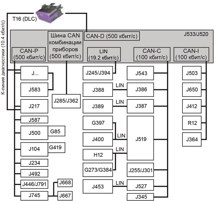
(Information presented on the website SKODABOOK.RU)
1.1. Structure of data transmission buses (decoding of electrical component designations is given at the end of the Manual, before the wiring diagrams; J... - engine control unit)
Safety precautions when working with ignition and fuel injection control systems
- To prevent injury and/or failure of electrical and electronic system components, the following must be observed:
- do not touch or disconnect the ignition system wiring while the engine is running/starter is rotating;
- disconnect/connect fuel injection system lines, ignition system wiring, as well as any diagnostic and measuring equipment only when the ignition is off;
- maintenance work on the electronic ignition system is not permitted for people with an implanted pacemaker.