




16.1. Double Clutch Assembly Details 1. Retaining ring; 2. Plate support, do not try to remove or lift even a little; 3. Dual clutch housing with installed clutch "K2"; 4. Sealing rings, 4 pcs.; 5. Outer plates, 4 pcs.; 6. Inner plates, 4 pcs.; 7. Thrust washer; 8. Retaining ring, after removing to install new plates, install a new ring of the same thickness; 9. Clutch cover; 10. Retaining ring, must be replaced, do not install wave retaining rings
Removal/installing the clutch cover
2. The clutch cover is held in place by a retaining ring, after which the cover can be lifted. The cover and retaining ring must be replaced after removal. Never install a new cap with a hammer, do not grasp it by the center hole and do not lubricate the center seal, otherwise a leak will occur (see illustration 16.2a). Handle the new cover only as shown in Illustration 16.2b.
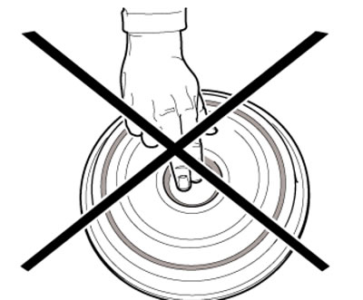
16.2a. Do not touch the middle pad
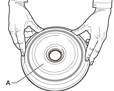
16.2b. Holding the clutch cover
3. Remove the DSG (see Section 15).
4. Unscrew the service hole plug (In the illustration 21.11 Chapter 1) next to the rocking support, and then unscrew the overflow tube located behind this plug - approximately 5 liters of working fluid will pour out. Screw in the overflow tube.
5. Unscrew the lid (1 in illustration 21.6 Chapter 1), tilt the filter (3) slightly so that the working fluid flows from it into the DSG, and remove the filter. Install a new sealing ring (2), after lubricating it with DSG fluid.
6. Wet the sealing ring in the receiving sleeve (see illustration 21.7 Chapter 1), install a new filter and tighten its cover with a torque of 20 Nm.
7. Fill the DSG with fresh working fluid (see Section 21 Chapter 1).
8. Remove the clutch cover retaining ring and lift it up with a screwdriver.
9. The clutch cover can be supplied with or without a bushing. Installation of a clutch without a sleeve is described in paragraphs 10-13, and installation of a clutch with a sleeve is described in paragraphs 14-16.
10. Clean the T10302 mounting sleeve and make sure it is free of scratches. Make sure the new clutch cover is dry and there is no grease on the center seal. Clean the end of the clutch shaft if necessary. Only the seal on the outer edge of the cover can be lubricated with DSG working fluid. Place the T10302 bushing on a flat surface.
11. Deform the center seal (In the illustration) new clutch cover (A). To do this, push the cover evenly and horizontally onto the T10302 bushing - the sealing edge is brought to the installation position. Remove the sleeve from the cover in an upward direction and install the sleeve onto the end of the clutch shaft.
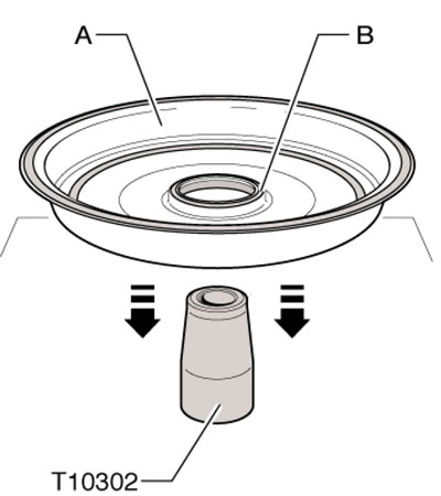
16.11. Deformation of the central seal
12. Close the lid (And in the illustration) through the T10302 bushing and evenly move it into the installation position. Do not allow even the slightest distortion.

16.12. Installing a cover supplied without a bushing
Note: Tool T30109 is used to mount the DSG.
13. Install a new retaining ring. While the retaining ring is not installed, you can carefully pry the cover off with a screwdriver (1 in the illustration) in its position (arrow).
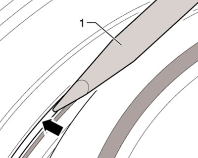
16.13. Installing the retaining ring
14. Do not remove the sleeve from the cover. Make sure the new clutch cover is dry and there is no grease on the center seal. Clean the end of the clutch shaft if necessary. Only the seal on the outer edge of the cover can be lubricated with DSG working fluid. Place the T10302 bushing on a flat surface.
15. Install the cover together with the bushing (see illustration), without allowing even the slightest distortion. Install a new snap ring. While the retaining ring is not installed, you can carefully pry the cover off with a screwdriver (1 in illustration 16.13) in its position (arrow).
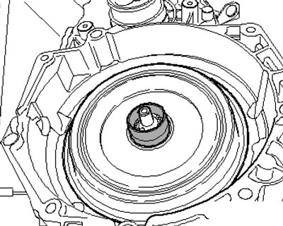
16.15. Installing the cover supplied with the bushing
16. After installing the retaining ring, the sleeve can be removed.
Clutch removal/installation
17. Remove the DSG (see Section 15) and secure it vertically so that the clutch is on top.
18. Remove the clutch cover (see subsection above). Remove the retaining ring (arrow on the illustration) and remove the cover (1).
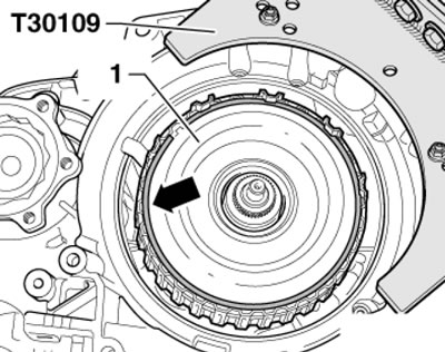
16.18. Clutch cover retaining ring
19. Remove the retaining ring (see illustration). Measure the thickness of this ring and prepare a new retaining ring of the same thickness.
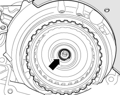
16.19. Clutch retaining ring
20. Carefully remove the clutch (And in the illustration) in the direction of the arrow without turning it to prevent the support plate or other clutch parts from falling. If the clutch has fallen apart, reassemble it as shown in Illustration 16.1.
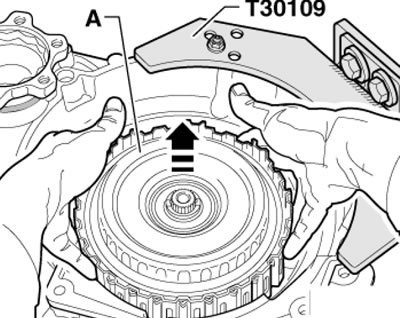
16.20. Removing the clutch
21. Pull out the drive shaft (And in the illustration) pump and set it aside. The drive shaft is inserted only after the new clutch has been installed.

16.21. Pulling out the pump drive shaft
22. The details of the supplied clutch are shown in the illustration. The cover of the new clutch is not secured with a retaining ring (5), it is seated in the clutch with a slight tension to prevent the clutch parts from falling during transportation. The cover can be carefully removed before installing the clutch.

16.22. Details of the supplied clutch 1. Clutch; 2. 10 retaining rings of different thickness, with a step of 0.1 mm; 3. Clutch cover, a sleeve is installed to protect the central seal, which should not be removed; 4. Cover retaining ring 3; 5. Cover retaining ring 3, do not install wave rings
23. Remove the new clutch from its packaging, pressing down on its cover to prevent the cover and the backing plate underneath from sliding off the inner plates. Pay attention to the correct position of the four piston rings (And in the illustration), - their joints should not be located on top of each other. Try turning the rings - they should move freely, without jamming.

16.23. Piston rings
24. Make sure the label is present (And in the illustration) on the clutch. If there is no mark, apply it with a marker opposite the tab (B) of the clutch cover. When installing, the cover tab will need to be positioned opposite this mark. If the cover is being installed on a new clutch, remove the retaining ring (1).

16.24. Lid position
25. Carefully remove the clutch cover in the direction of the arrows (see illustration) and put it aside. Do not remove or attempt to lift the plate support, otherwise the plates may rotate. Place the clutch aside so that it does not fall.

16.25. Removing the cover
26. Install the T10303 holding device onto the mounting surface (arrow on the illustration) clutch covers.

16.26. Installation of the T10303 device
27. Ask an assistant to hold the T10303 device (see illustration) and carefully install the clutch in the direction opposite to the arrow (see illustration 16.20), without allowing it to fall. Do not remove tool T10303 until the clutch cover has been installed.
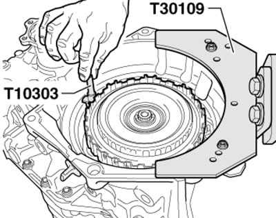
16.27. Holding the T10303 device
28. Select a 2mm thick snap ring from the clutch kit and temporarily install it (see illustration 16.19).
29. Install the MP3-447 or VW387 holder with a plunger indicator on the DSG flange. Press the indicator plunger against the DSG drive shaft (see illustration 16.29a), reset the indicator, lift the clutch to the stop and record the result. Then press the plunger of the indicator against the hub of the large support plate in the gap of the retaining ring (see illustration 16.29b). reset the indicator, lift the clutch to the stop and record the result. Determine the thickness of the required retaining ring. To do this, subtract the first measurement from the second result, add 1.85 mm and round down to 0.1 mm. Remove the temporarily installed 2.0 mm thick snap ring and replace it with a snap ring of the required thickness.
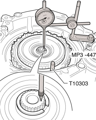
16.29a. Dimension #1

16.29b. Measurement #2
Note: Retaining rings may only be installed once.
30. Insert the pump drive shaft, turning it slightly (see illustration).
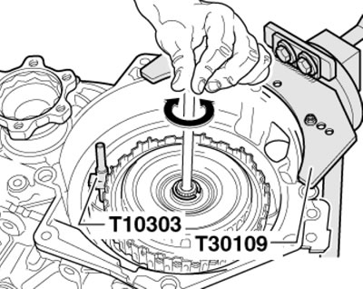
16.30. Installing the pump drive shaft
31. Insert the clutch cover so that its tab (In illustration 16.24) was aligned with the mark (A) on the clutch. Install a new retaining ring (1).
32. Remove tool T10303 and install the clutch cover (see subsection above).
33. Install the DSG and, using the diagnostic tool, apply the basic settings for the unit "Mechatronic".