



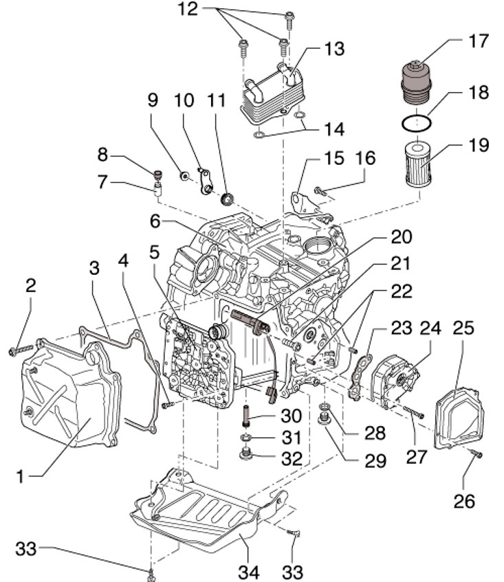
14.1. Location of serviceable components outside the DSG 1. Oil pan; 2. Pan mounting bolts 1, 5 pcs., subject to replacement; 3. Oil pan gasket 1, subject to replacement; 4. Bolts, block 5 fastenings, 10 pcs., subject to replacement, 5 Nm, then tighten to an angle of 90°; 5. Block "Mechatronic" "J743", with sealing rings on the connector that are subject to replacement; 6. DSG; 7. Breather, pressed into the DSG, must be replaced after removal; 8. Breather cap 8; 9. Nut, 20 Nm, subject to replacement; 10. Selector mechanism lever, with axis; 11. Axle gasket 10, installed with the inscription facing outward; 12. Radiator mounting bolts 13, subject to replacement, 3 pcs., 20 Nm, then tighten to an angle of 90°; 13. DSG working fluid radiator; 14, 18. Sealing rings, subject to replacement; 15. Selector cable holder; 16. Holder mounting bolts 15, 2 pcs., subject to replacement, 20 Nm, then tighten to an angle of 90°; 17. Filter housing, 20 Nm; 19. Filter element; 20. Sensor "G182" of the input shaft speed with the sensor "G509" of the clutch temperature; 21. Bolt, subject to replacement, 10 Nm; 22. Centering fingers of pump 24, 2 pcs.; 23. Gasket, subject to replacement; 24. DSG working fluid pump; 25. Pump cover 24, with vulcanized gasket, subject to replacement; 26. Cover fastening bolts 25, 4 pcs., subject to replacement, 8 Nm; 27. Pump mounting bolts 24, 4 pcs., subject to replacement, there are different bolts; 28. Plug sealing ring 29, subject to replacement; 29. Drain plug (45 Nm), not used, control plug 32 and tube 30 are used to drain the working fluid; 30. Plastic overflow tube for 8 mm hexagon, 3 Nm, the length of the tube determines the level of the working fluid; 31. Sealing ring, subject to replacement; 32. Service hole plug, 45 Nm; 33. Plate mounting bolts 34, 4 pcs., 32 Nm; 34. Protective plate, installed on new DSG
Oil pan
1. Disconnect the negative cable from the battery.
2. Remove the sound insulation under the engine compartment (see Chapter 11).
3. Give the nuts (2 in the illustration) bracket (1) and remove the bracket from the studs on the pan at the front of the DSG.
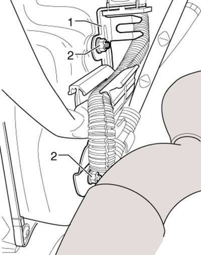
14.3. Fastening the bracket to the DSG oil pan
Text taken from this website (www.SkodaBook.ru)
4. If present, unscrew the bolts (arrows in illustration 21.10 Chapter 1) and remove the protective plate (A) under the DSG. Place a tray under the DSG to collect the leaking fluid and put on safety glasses.
5. Unscrew the service hole plug (In the illustration 21.11 Chapter 1) next to the rocking support, and then unscrew the overflow tube located behind this plug - approximately 5 liters of working fluid will pour out. Screw in the overflow tube.
6. Discharge yourself from static electricity, turn the bayonet lock (1 in the illustration) connector to the left and disconnect the connector.
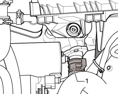
14.6. Block connector retainer "Mechatronic"
7. Remove 5 bolts (see illustration) in a diagonal order and remove the oil pan together with the gasket. At the same time, the remaining working fluid is poured out.
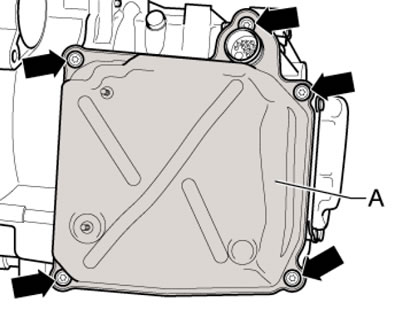
14.7. Oil pan mounting bolts
8. Installation is carried out in reverse order. Replace the pan gasket and connector sealing rings (see illustration). Lubricate the sealing rings with DSG fluid beforehand. When installing the pan, make sure not to pinch the wiring. Use new pan mounting bolts.
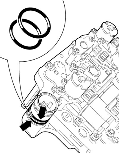
14.8. Connector sealing rings
9. When docking the connector (And in the illustration) proceed as follows. Arrows (D) on the block "Mechatronic" (B) and on the connector, as well as the protrusion (C), must be in line. After this, carefully connect the connector until it stops and secure it by turning the lock in the direction of the arrow.
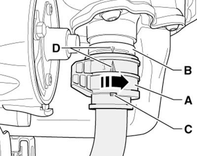
14.9. Connecting the connector
10. Replace the filter and fill the working fluid (see Section 21 Chapter 1).
DSG fluid radiator
11. Set the selector lever to position "P".
12. Remove the top engine cover and air cleaner (see Chapter 4).
13. Remove the battery and its holder (see Chapter 5).
14. Place a lint-free cloth over the DSG and DSG fluid radiator to collect any leaking coolant.
15. Mark the coolant hoses relative to the radiator (to avoid confusion during installation), clamp them with MP7-602 clamps and disconnect the hoses from the DSG fluid radiator (see illustration).
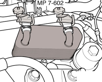
14.15. DSG radiator coolant lines
16. Remove the bolts (And in the illustration) and remove the DSG fluid radiator (B). Replace the sealing rings (C). Do not allow coolant to come into contact with the DSG or the oil passages.
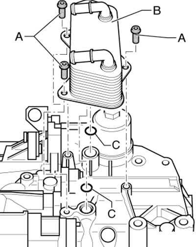
14.16. Removing the DSG fluid radiator
17. Installation is carried out in reverse order. Use new bolts. Finally, adjust the coolant level, replace the DSG fluid and its filter (see Chapter 1).
Mechatronic unit "J743" and sensor assembly "G182" and "G509"
18. Set the selector lever to position "P" and disconnect the negative cable from the battery.
19. Remove the sound insulation under the engine compartment and the front left wheel arch liner (see Chapter 11).
20. Remove the shroud together with the fans from the engine cooling system radiator (see Chapter 3).
21. If present, unscrew the bolts (arrows in illustration 21.10 Chapter 1) and remove the protective plate (A) under the DSG.
22. If present, remove the connecting hose between the intercooler and the boost air pipe (see Chapter 4).
23. Give me the nuts (2 in illustration 14.3) bracket (1) and remove the bracket from the studs on the sump at the front of the DSG. Lift the wiring in the sump area and secure it. Place a container under the DSG to collect the working fluid and put on safety glasses.
24. Unscrew the service hole plug (In the illustration 21.11 Chapter 1) next to the rocking support, and then unscrew the overflow tube located behind this plug - approximately 5 liters of working fluid will pour out. Screw in the overflow tube.
25. Remove the bolts (A-C in Illustration 5.16 Chapter 6) and remove the rocker support. The DSG can then be pushed back slightly towards the subframe to improve access.
26. Remove the bolts (see illustration) and remove the cover (A) of the pump. Otherwise, when removing the unit "Mechatronic" the long sensor will be damaged "G195"/"G196" dSG output speed.
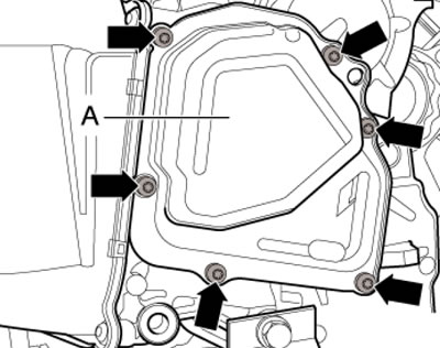
14.26. Fastening the pump cover
27. Remove any static electricity from yourself and turn the bayonet lock (1 in illustration 14.6) connector to the left and disconnect the connector.
28. Remove 5 bolts (see illustration 14.7) in a diagonal order and remove the oil pan together with the gasket. At the same time, the remaining working fluid is poured out.
29. Gently press the locking mechanism with a small screwdriver (1 in the illustration), to remove the connector (2) of the sensor assembly "G182"/"G509", and disconnect the connector using the second screwdriver (2). Release the wiring from the holders (arrows).
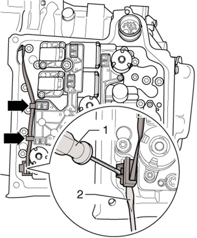
14.29. Removing the fixation of the connector of the sensors assembly "G182" and "G509"
Caution: Do not pry (just press) locking mechanism to prevent the connector lock from breaking; do not pull on the wiring. If the connector retainer is damaged, the Mechatronic unit will need to be replaced.
30. Remove the nine block mounting bolts "Mechatronic" in order (10-1 in the illustration).
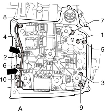
14.30. Block mounting bolts "Mechatronic"
Note: Reuse of bolts is not permitted.
31. Pull out the block "Mechatronic" from the DSG housing so that the sensor lever (In the illustration) on the back side was no longer in the DSG housing.
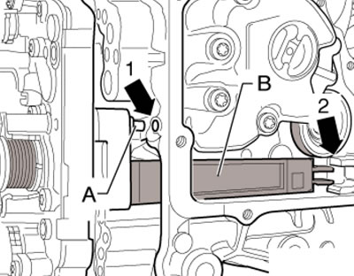
14.31. Preliminary block output "Mechatronic"
32. Remove the block "Mechatronic", as shown in the illustration. Do not lift the unit by the sensor lever or place the unit on this lever. If the lever is damaged, the entire unit will need to be replaced.
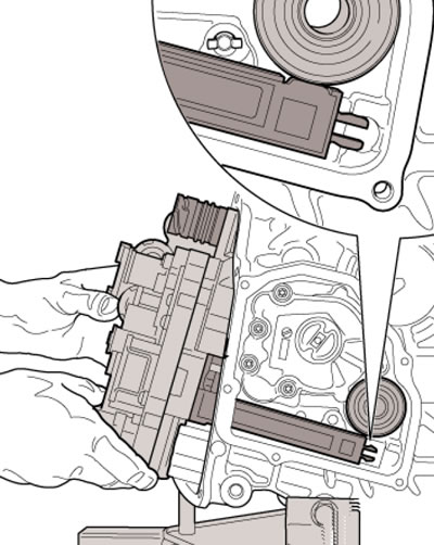
14.32. Removing the block "Mechatronic"
33. Hold the block when carrying "Mechatronic" only as shown in the illustration, otherwise it may be damaged.
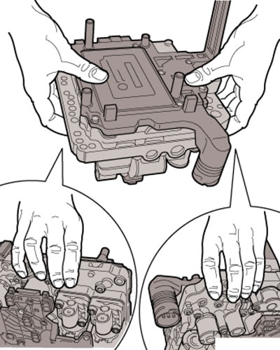
14.33. Correct holding of the Mechatronic unit
34. If necessary, unscrew the bolt (In the illustration), carefully pry up the assembly (A) of the "G182" input speed sensor and the "G509" clutch temperature sensor with a screwdriver or pull it out with pliers. Disconnect the connector (C) and remove the sensor assembly.
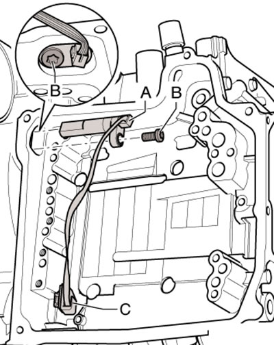
14.34. Fastening sensors "G182"/"G509"
Caution: Do not pull on the wiring, otherwise the sensor assembly will need to be replaced. Before installing the sensor assembly, moisten it with DSG fluid.
35. Installation is carried out in reverse order. Pay attention to the correct placement of the finger (And in illustration 14.13) in the hole (1) in the DSG housing and the sensor lever (B) in the guide (2). Do not pinch the wiring (And in the illustration 14.30) sensor assemblies, do not damage the long sensor on the back of the unit "Mechatronic". Use new block mounting bolts. Tighten them in sequence (1-10): first by hand, then with a force of 5 Nm, and then tighten to an angle of 90°. First, secure the wiring in the upper holder, and then in the lower sensor, after which connect the connector (A). Observe the installation features of the oil pan. Use a new pump cover and new pump cover mounting bolts. Finally, use the diagnostic tool to apply the basic settings for the Mechatronic unit.
36. Remove the sound insulation under the engine compartment and the front left wheel arch liner (see Chapter 11).
37. If present, unscrew the bolts (arrows in illustration 21.10 Chapter 1) and remove the protective plate (A) under the DSG. Place a container under the DSG to collect the working fluid and put on protective glasses.
38. Unscrew the service hole plug (In the illustration 21.11 Chapter 1) next to the rocking support, and then unscrew the overflow tube located behind this plug - approximately 5 liters of working fluid will pour out. Screw in the overflow tube.
39. Remove the bolts (see illustration 14.26) and remove the pump cover (A).
40. Unscrew the bolts and remove the pump (1 in the illustration) from the guide pins and the DSG drive shaft. Pay attention to the installation locations of the different bolts so as not to mix them up later.
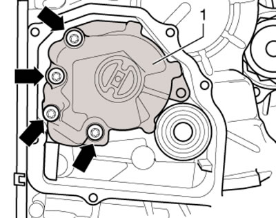
14.40. Pump fastening
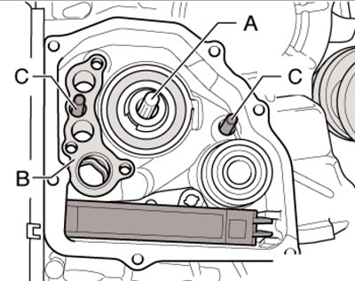
41. Press in the drive shaft (And in the illustration) in DSG until it stops and turn it a little. Replace the DSG bracket (B) and ensure that both centring pins are present in the DSG housing.
14.41. Preparing for pump installation
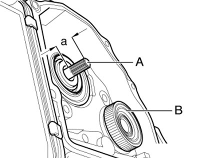
42. Make sure that the shaft (And in the illustration) protrudes by a distance (a) of approximately 23 mm. If necessary, remove metal filings from the rotor (B), avoiding demagnetization of the rotor. Remove the gasket between the pump and DSG, clean their mating surfaces and install a new gasket. If necessary, secure the gasket with working fluid.
14.42. Drive shaft projection
43. Slide the pump onto the shaft and tighten its mounting bolts. If all 4 flat head bolts are used, tighten them to 5 Nm and then tighten them to a 90° angle. If one countersunk head bolt is used, screw it into the top hole (see illustration 14.40); in this case, tighten this bolt with a force of 8 Nm, and the remaining 3 bolts - in two stages: first with a force of 8 Nm, and then tighten to an angle of 90°.
44. Install a new pump cover and new mounting bolts. Replace the filter and fill the working fluid (see Section 21 Chapter 1).