
Note.
- Necessary special devices, control and measuring devices, as well as auxiliary means:
- Assembly stand -MP9-101-.
- Hook -3438-.
- Puller -T10323-
- Pressure piece -T10368-.
- Puller -T10373-.
- Pressure piece -T10376-.
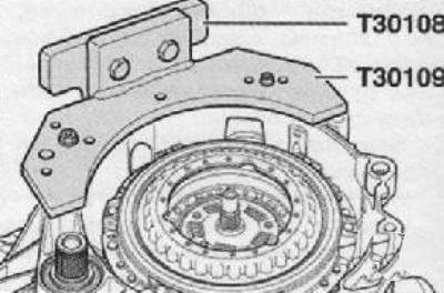
- Gearbox mounting tool -T30108-.
- Gearbox mounting tool -T30109 (VW 353) -. The gearbox has been removed.
- The mechatronics for the manual gearbox -J743- is mounted on the gearbox.
1. Dismantle both covers of the bleed pipes -arrows- and plug them with suitable plugs so that no oil can escape.
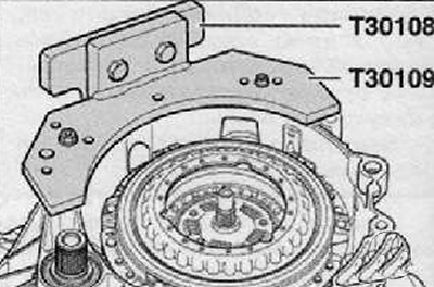
2. The gearbox must be installed on the tool for fixing the gearbox -T30109 (VW 353) - clutch up.
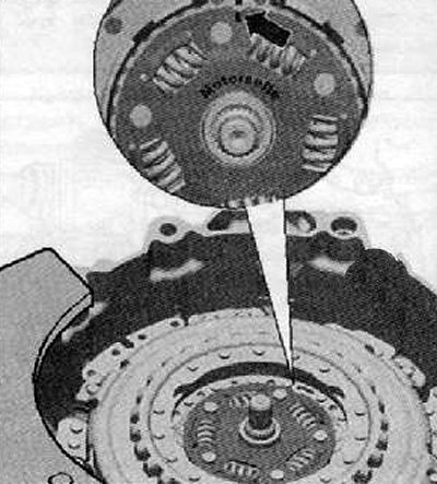
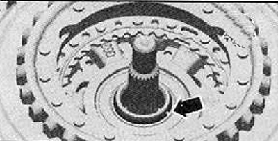
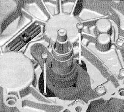
3. Remove the retaining ring of the hub -arrow-.
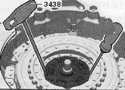
4. Use the hook -3438- -A- and the screwdriver -B- to remove the hub.
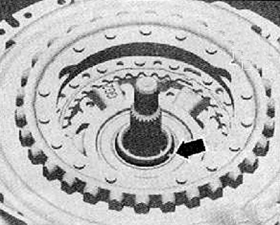
5. Remove the clutch circlip (arrow), as shown in the figure below.
Note.
- It may happen that the clutch is so tight against the circlip that the circlip
- the ring is very strongly wedged. In this case, it is possible to press the clutch slightly downwards as described below. This will take the load off the retaining ring. Do not tap on the clutch or on the shaft with a hammer!
- Retaining ring (arrow) should always be replaced.
Note. If the circlip cannot be removed, press the clutch down slightly as described below.
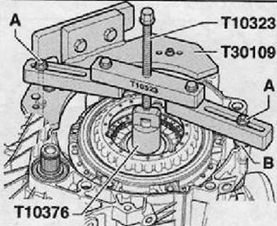
6. Install puller (Т10323) so that it is in a position parallel to the flange of the clutch housing, as shown in the figure below.
7. Align the distances, e.g. using washers (IN) with a total thickness of 15 mm.
8. Attach the puller (Т10323) with screws (A), as shown in the figure below.
Note. screws (A) should be secured with nuts.
9. The clutch should be pressed carefully down with the spindle.
10. Remove puller (Т10323), shown in the figure below.
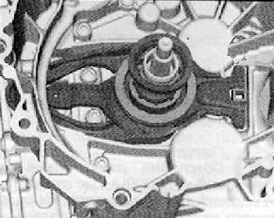
11. Remove clutch circlip -arrow-.
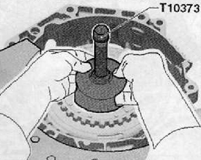
12. Inserting a special puller into the clutch (Т10373), as shown in the figure below, then remove the clutch.
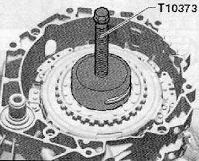
13. Remove the clutch together with the puller (Т10373), as shown in the figure below.
14. Remove the large release fork along with washers and release bearing as shown in the figure below.
Note. The upper part of the guide bush cannot be removed separately. It is always removed and installed together with the lower part of the guide bush and the small release bearing.
15. Unscrew the fastening screws and remove the small clutch release fork, as shown in the figure below.
16. Remove stop (1) and unscrew the bolt (2), as shown in the figure below.

Note. Before proceeding with the installation, the clutch should be inspected to see if it needs to be adjusted or not.