



Note: The DSG is removed downwards together with the angular gear, separately from the engine.
1. Set the selector lever to position "P".
2. Disconnect the negative cable from the battery.
3. Remove the top engine cover and air cleaner (see Chapter 4).
4. Remove the battery and its holder (see Chapter 5).
5. Remove the windshield fairing (see Chapter 11).
6. Release the lock washer (1 in illustration 13.9) and remove it upwards. Then remove the lock washer (3) upwards. Press the selector cable (2) away from the selector mechanism axis in the direction of the arrow and place it on top.
Note: Reinstallation of lock washers (1 and 3) is not permitted. Do not bend the cable or push it backwards from the support (the cable is removed from the holder when the selector mechanism is removed).
7. If the lock washers cannot be removed without damaging the cable, two bolts can be removed (1 in the illustration) and remove the cable support (2).
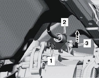
15.7. Fastening of the cable support
8. Disconnect the wire (1 in the illustration) from the starter solenoid valve, disconnect the connector (2) and remove the ground wire (3) from the console. Remove any electrostatic charge from yourself and disconnect the connector (4) by turning its lock. Unscrew the starter mounting bolts and remove it (see Chapter 5). Disconnect all engine/transmission wiring connectors accessible from the top.
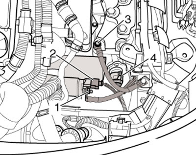
15.8. Starter and DSG connectors
9. Remove one bolt (And in the illustration) dSG mounts, located in the opening under the starter, using the XZN14 head (T10061).
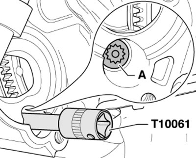
15.9. DSG mounting bolt accessible through starter opening
10. Place a lint-free cloth over the DSG and DSG fluid radiator to collect any leaking coolant. Mark the coolant hoses relative to the radiator (to avoid confusion during installation), clamp them with MP7-602 clamps and disconnect the hoses from the DSG fluid radiator (see illustration 14.15). Seal the radiator connections.
11. Give the nuts (2 in illustration 14.3) bracket (1) and remove the bracket from the studs on the pan at the front of the DSG.
12. Install the T30099 tool (see illustration 5.10 Chapter 6) and unload the power unit supports.
13. Loosen the hub bolts and front wheel mounting bolts, raise the vehicle and remove the front wheels.
14. Remove the sound insulation under the engine compartment and the front wheel arch liners (see Chapter 11).
15. Loosen the clamps (1 in the illustration) and remove the left boost air hose (2).
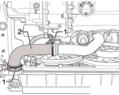
15.15. Left charge air hose clamps
16. Pull out the fasteners and remove the right boost air hose (see illustration).
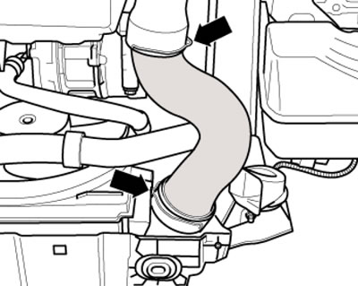
15.16. Right charge air hose
17. Remove the shroud with fans from the engine cooling system radiator (see Chapter 3).
18. If present, unscrew the bolts (arrows in illustration 21.10 Chapter 1) and remove the protective plate (A) under the DSG.
19. Separate the exhaust system on the double clamp and remove the exhaust system bracket from the subframe (see illustration 5.14 Chapter 6). Tie up the exhaust pipe. Do not allow the flexible section to bend more than 10°.
20. Mark the position of the cardan shaft with the flexible disk relative to the output flange of the angular transmission, and then release the fastener of the cardan shaft to the output flange of the angular transmission (see illustration 5.15 Chapter 6).
21. Remove the rocker support from the DSG by unscrewing the bolts (In and Sleep illustrations 5.16 Chapter 6).
Note: The swing support is removed together with the subframe.
22. After removing the rocker support, the power unit tilts forward slightly, so be careful not to damage the gasket (see illustration 5.17 Chapter 6) in the flange of the cardan shaft. Push the power unit forward, pull the cardan shaft off the angular transmission flange and tie the shaft to the body.
23. Disconnect the engine oil temperature and level sensor connector on the bottom of the engine oil pan (withm. Chapter 2).
24. Secure the subframe and remove it together with the swing arm, anti-roll bar, consoles, steering gear and suspension arms.
25. On diesel models with a diesel particulate filter, remove it together with the bracket (see Chapter 4).
26. If present, unscrew the bolts (1 in illustration 4.40 Chapter 1) and remove the heat shield (A) of the right drive shaft. Disconnect the left and right drive shafts (C) from the DSG flange shafts and support the drive shafts on the suspension struts as far back as possible. Be careful not to damage the protective coating on the shafts.
27. Give me the nuts (1 in the illustration) supports (A) DSG on angular transmission. Loosen the nuts (2 and 3) of the DSG support on the engine.
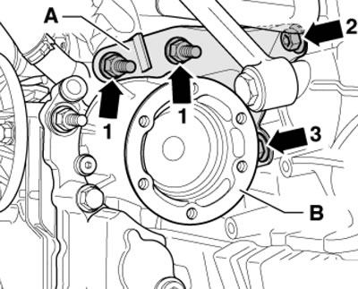
15.27. DSG support fastening
Note: It will not be possible to loosen the nut (3) completely, as it will rest against the right drive shaft; the DSG support can only be removed after the DSG has been removed from the engine.
28. Remove the bolts (1 and 2 in the illustration), lower the power unit evenly onto the spindles of the T30099 device and remove the support console (A).
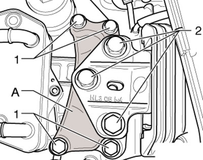
15.28. Fastening the DSG support and its console
29. Evenly lower/raise the power unit on the spindles of the T30099 device so that the distance (and in the illustration) was 100-110 mm.
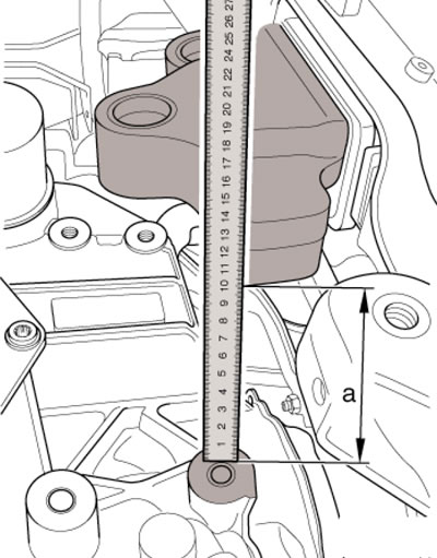
15.29. Distance for lowering DSG
30. Attach support plate #3282 with adapters to DSG as shown in the illustration and secure DSG with straps to this plate. Place a transmission jack under the DSG and secure the support plate to it.
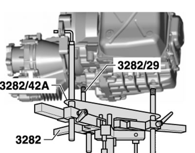
15.30. Devices for holding the DSG on a jack
31. Remove the DSG mounting bolt to the engine near the angular gear (see illustration 5.29 Chapter 6).
32. Remove the remaining bolts (6-9 in the illustration), slide the DSG off the mounting bushes (A) and pull it away from the engine by approximately 30 mm.
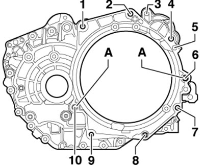
15.32. Centering bushings (A) and DSG mounting bolts A. Centering bushings; 1,2,4. Bolts M12x55, 80 Nm; 3. Bolt M10x45 for fastening the starter to the DSG, 40 Nm; 5. Bolt M 10x40 for fastening the starter to the DSG, 40 Nm; 6. Bolt M 12x65, 80 Nm; 7-9. Bolts M 10x50, 40 Nm; 10. Bolt M 12x65, inserted from the engine side, 80 Nm
33. Give me the nuts (2 and 3 in illustration 15.27) fastening the DSG support to the engine and remove the support. Carefully tilt the DSG towards the left side member, changing its position on the spindles of support #3282. Lower the DSG from the engine compartment, removing the selector cable from its holder. Remove the DSG, paying attention to its connecting lines.
34. Check and, if necessary, replace the needle bearing in the crankshaft (see Chapter 2). Lightly lubricate the needle bearing and the end of the input shaft (not the splines) with G052 133A2 high temperature grease.
35. Make sure that the centering bushings are present (And in the illustration 15.32).
36. Installation is carried out in reverse order. The tightening forces for the DSG fasteners to the engine are shown in Figure 15.32. Tighten the DSG support console mounting bolts with a force of 60 Nm, and then tighten to an angle of 90°; tighten the DSG support mounting bolts to the console with a force of 40 Nm, and then tighten to an angle of 90°.