



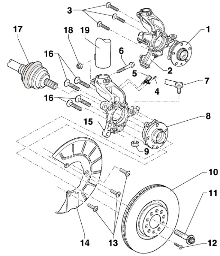
2.1. Installation details of the steering knuckle and the front wheel hub assembly 1. Hub assembly (hub with bearing) models with FS-III brakes (3 attachment points), with built-in sensor rotor 5; 2. Steering knuckle for models with FS-III brakes (3 attachment points); 3, 16. Bolts M12x1.5x45, subject to replacement, 70 Nm, then tighten to an angle of 90°; 4. Bolt M6x16, 8 Nm; 5. ABS wheel sensor, before installation, clean the inner surface of the mounting hole and apply grease G 000 650 to it; 6. Bolt, inserted from behind; 7. Tie rod end; 8. Hub assembly (hub with bearing) models with FN3 brakes (4 attachment points), with built-in sensor rotor 5; 9. Self-locking nut, subject to replacement, 20 Nm, then tighten to an angle of 90°; 10. Brake disc, ventilated; 11. Hub bolt, to be replaced, 70 Nm, then tighten to an angle of 90°; 12. Brake disc mounting bolt, 4 Nm; 13. Bolts M6x12 for mounting the shield 14.12 Nm; 14. Brake mechanism shield; 15. Steering knuckle for models with FN3 brakes (3 attachment points); 16. Self-locking nut M12x1.5x45, subject to replacement, 70 Nm, then tighten to an angle of 90°; 17. Drive shaft; 18. Self-locking nut, to be replaced, 70 Nm, then tighten to an angle of 90°; 19. Suspension strut
Unscrewing and tightening the hub bolt
Caution: After removing the hub bolt, do not apply load to the wheel bearing (do not lower the car to the ground), otherwise the bearing will be damaged. When the vehicle is on the ground, do not loosen the hub bolts more than 90°. If you need to roll the vehicle without the drive shaft, install the outer CV joint and tighten the old hub bolt to 120 Nm.
2. Provide access to the hub bolt. To do this, depending on the wheels installed, remove the decorative cap of the steel wheel rim or the central protective cover of the alloy wheel rim (see illustrations 6a-b of the Introduction). Wheels with standard alloy wheels should be removed, the protective plug of the hub bolt should be pushed out from the inside and the wheels should be installed back.
3. Loosen the hub bolt (see illustration) no more than 90°.
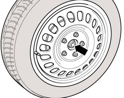
2.3. Hub bolt
4. Raise the vehicle enough to relieve the front suspension (the wheels should not touch the ground).
5. Have an assistant depress the brake pedal to stop the wheel from spinning and remove the hub bolt.
6. With the clutch pedal depressed, tighten the new hub bolt to 70 Nm.
7. Lower the vehicle to the ground, tighten the hub bolt to a 90° angle and cover it with a protective plug or cover/cap.
Removal and installation of the hub assembly
8. Remove the hub bolt (see subsection above).
9. Remove the front wheel.
10. Remove the caliper with the anchor bracket and hang them on the body parts with a wire, without disconnecting the brake fluid hose (see Chapter 9). The hose should not be tense.
11. Remove the ABS wheel sensor and brake disc (see Chapter 9).
12. Press the drive shaft out of the hub as far as possible towards the transmission.
13. Remove the bolts (see illustration) and remove the hub assembly from the steering knuckle.
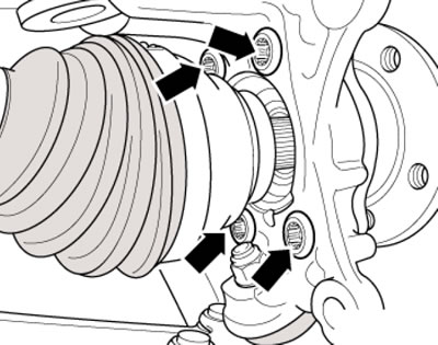
2.13. Hub assembly mounting bolts
Material is available on the website (Skodabook.ru)
14. Installation is carried out in reverse order. Tighten the front hub assembly mounting bolts to 190 Nm (on models with FN3 brakes) or 30 Nm (on models with FS-III brakes).