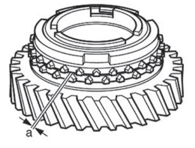
Checking the wear of the synchronizer locking rings for 1st, 2nd and 3rd gears
Install the synchronizer locking ring, outer race (ring) and inner ring on the cone of the driven gear, measure the size (a) with a feeler gauge.
| Size "a" | Admission of new parts | Wear limit |
| 1st, 2nd and 3rd gears | 1.2...1.8 mm | 0.5 mm |
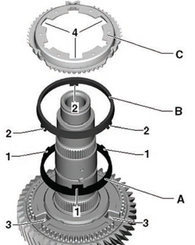
- Place the inner ring (A) onto the driven gear (3).
- Place the outer race (B) as shown in the figure below. The projections (2) of the outer ring (B) must enter the recess of the driven gear (3).
- Install the synchronizer locking ring (C). The driver projections (1) of the inner ring (A) must enter the deeper recesses (4) of the synchronizer locking ring (C).