



Contents: Engine oil ⬇ Visual inspection of leaks ⬇ Checking and adjusting the level ⬇ Coolant - checking and adjusting the…⬇ Windscreen washer fluid ⬇ Brake fluid ⬇ 5-speed manual transmission oil ⬇ Oil for 6-speed manual transmission,…⬇ DSG transmission fluid ⬇
Note: Regardless of the inspection intervals according to the maintenance schedule (see Section 3), do not allow fluids to leak under the vehicle - such leaks indicate a malfunction that should be corrected immediately.
Note: A description of how to check the battery electrolyte level is given in Section 17.
1. Liquids are an integral part of lubrication systems, cooling systems, windshield washing systems, braking systems and others. Due to the gradual consumption and contamination of fluids during normal vehicle operation, they should be replaced periodically. Add only fluids that meet Specification requirements.
Note: When checking the fluid level, the vehicle must be on a level, horizontal surface.
Engine oil
Note: Engine oil consumption depends on driving style and vehicle operating conditions, but should not exceed 0.5 l per 1000 km. Higher oil consumption is a sign of wear on the valve stem seals and/or piston rings, or engine shaft seals. New engines reach normal oil consumption only after approximately 5,000 km.
Visual inspection of leaks
2. If the engine is oily and has high oil consumption, check the following areas for leaks:
- engine oil pan gasket;
- engine oil drain plug seal;
- seal D/V engine oil pressure;
- oil filter gasket;
- gasket between block and cylinder head;
- cylinder head cover gasket;
- oil filler cap seal;
- crankshaft and camshaft oil seals.
Since when there is a leak, the oil spreads over a large surface area of the engine, it is difficult to localize it immediately. To detect leaks, proceed as follows:
3. Clean the engine by covering the generator and fuse box with a plastic bag, spraying the engine with a regular cold cleaner and after a short time washing with water.
4. Sprinkle the mating surfaces and seals on the outside of the engine with lime or talc.
5. Check the engine oil level and correct it if necessary (see below).
6. In order to warm up the oil, take the car for a test drive - the viscosity of the heated oil will decrease, and it will appear faster in the places of leaks.
7. Finally, examine the engine by shining a lamp on it. Locate and repair leaks. If it is not possible to detect leaks using the described method, you can use a special additive to engine oil to detect its leaks under ultraviolet light (see directions for use included with this supplement).
Checking and adjusting the level
8. Check the engine oil level using the dipstick with a yellow handle (4 in the illustrations of Section 1), installed in the guide tube.
9. The engine oil level should be measured on a cold engine, or at least 3 minutes after turning off a warm engine.
Note: If you start measuring immediately after turning off the engine, the oil remaining in the upper part of the engine will not have time to drain, and the measurement results will be erroneous.
10. Remove the feeler gauge from the guide tube and wipe the blade dry with a clean, lint-free cloth or paper towel. Insert the dipstick all the way back into the guide tube and pull it out again.
11. The height of the oil-wetted section of the dipstick will correspond to the oil level in the engine. This level must be in the area (b in the illustration) dipstick. If the level has dropped to area (c), add approximately 1 liter of engine oil in small portions until the level rises to area (a), as described below. If the level is above area (a), the oil must be pumped out, otherwise the engine seals and catalytic converter may be damaged.
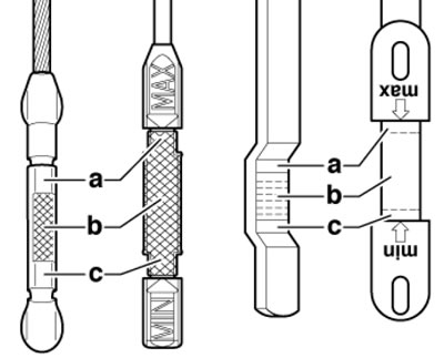
4.11. Engine oil dipstick areas
12. To add oil, remove the oil filler cap, - with the oil can icon, (3 in the illustrations of Section 1). Add oil in small portions, no more than 0.5 l. After adding oil, wait a few minutes for its level to stabilize, then repeat the check. If necessary, make adjustments again. If dirt is found on the filler cap, wash it with gasoline. Finally, tighten the oil filler cap tightly.
13. Checking the oil level is an important preventative procedure that should be performed as often as possible, and also before every long trip. In addition, you should also pay attention to the condition of the oil: a milky color or the presence of water droplets in the oil may indicate a leak in the cylinder head gasket or a crack in the head or cylinder block, as a result of which coolant gets into the oil. In this case, the engine should be repaired immediately. Each time you measure the oil level, run your thumb and forefinger across the dipstick blade before wiping it clean. If dirt or metal particles are found stuck to the dipstick, the oil and filter should be replaced (see Section 6).
Coolant - checking and adjusting the level and condition, identifying leaks
Caution: Avoid contact of antifreeze with skin or painted surfaces of the vehicle. If this does happen, immediately flush away the antifreeze with plenty of water. Antifreeze is extremely toxic, so do not leave it unattended in an open container or spilled on the floor: children or animals may be attracted to the sweet smell of antifreeze and may drink it.
Caution: Do not remove the filler cap of the expansion tank until the engine has cooled down!
Note: All engines (cast iron and aluminum) they are filled with coolant with purple G12-Plus-Plus antifreeze, which provides optimal protection against freezing, corrosion and sediment, and does not require replacement throughout the life of the engine.
14. The vehicles in question are equipped with a compensating cooling system with excess pressure. The expansion tank is located on the left side of the engine compartment (1 in the illustrations Section 1). As the engine warms up during its operation, the expanding coolant (coolant) fills the tank. When the engine cools down, the coolant automatically flows back into the cooling system, which ensures that the fluid level is maintained at a constant level.
15. The coolant level should be checked regularly, at least every month, and before each long trip.
16. At room temperature, the coolant level in the expansion tank is considered normal if the coolant reaches the area between the "MIN" and "MAX" marks on the tank wall (see illustration). When the engine is warm, the coolant level may be slightly above the "MAX" mark. If necessary, add coolant to the expansion tank through the filler neck, then close it securely with the cap. When topping up, do not allow the coolant level to rise above the upper limit. To warn of a low brake fluid level, there is a corresponding indicator lamp in the instrument cluster (see Section 13 Chapters "Controls and operating techniques").
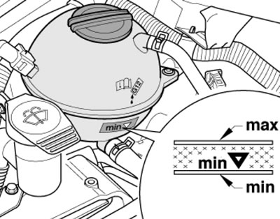
4.16. Markings on the expansion tank
17. When filling the cooling system, be sure to use the mixture specified in the Specifications.
Note: If there is a need to fill the cooling system on the road, then in the summer you can use clean water, but not another type of antifreeze (not specified in the Specifications) type. The required type of antifreeze can be added later, but as quickly as possible.
18. If the coolant level drops rapidly, visually inspect the cooling system for leaks - these are usually detected by a white or rust-colored coating in the area surrounding the leak.
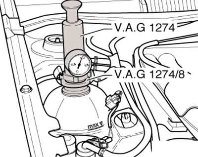
4.18. Checking the cooling system under pressure
Check the condition of the hoses and the reliability of their fastening to the pipes; replace damaged hoses and clamps (see also Section 5). Cracks are easier to detect if you pinch the hose.
Check the expansion tank cap seal.
Pressure test the cooling system. To do this, warm up the engine to operating temperature, carefully remove the expansion tank cap and install the VAG 1274 pressure booster with the VAG 1274/8 adapter on its neck (see illustration 4.18). Create a pressure of about 1.0 bar - it should not decrease; if the pressure drops, check the cooling system for leaks.
Note: If the VAG 1274B tool is used to build up pressure, the VAG 1274B/1 connecting hose must be installed between it and the adapter.
You should also check the EGR radiator of diesel models and the oil cooler (there may be an internal leak).
19. If no leaks are found, check the tightness of the expansion tank cap. To do this, first pull the lid valve and release it - it should return to its original position. Make sure the valve seat is free of dirt and damage. Then lubricate the cover seal with coolant and connect the VAG 1274 pressure build-up tool with the VAG 1274/9 adapter to the cover (see illustration). When creating pressure, watch the bypass valve in the cap - it should open at a pressure of 1.4-1.6 bar. Otherwise (if the valve opens at a lower pressure or does not open at the specified pressure) replace the expansion tank cap.
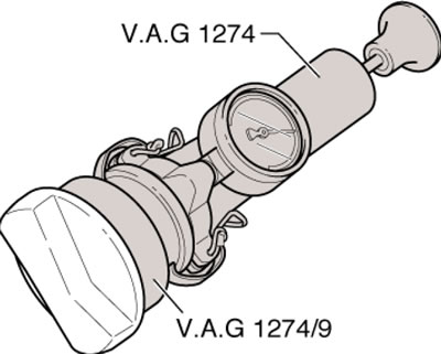
4.19. Checking the expansion tank cap
Note: If the VAG 1274B tool is used to build up pressure, the VAG 1274B/1 connecting hose must be installed between it and the adapter.
20. You should also check the condition of the coolant - it should be relatively clean. If the liquid is brown or rusty in color, it should be drained, the cooling system should be flushed, filled with a new mixture and bled (see Chapter 3).
21. To check the frost resistance of the coolant, use a hydrometer.
Windscreen washer fluid
22. Windshield and rear window washer fluid, as well as headlights, should be added to the appropriate reservoir through the filler neck (2 in the illustrations of Section 1).
23. In regions with a moderate climate, you can use regular water to wash the glass, but it is recommended to add a glass cleaner or, in some cases, a wax remover (see Specifications). The reservoir should be filled no more than two-thirds full to allow for expansion of the water as it turns to ice. In cold climates, a special windshield washer fluid should be used to lower the freezing point of the liquid. It is usually sold in concentrated or ready-made form. Mix concentrated antifreeze with water according to the manufacturer's instructions on the packaging.
Caution: Do not use antifreeze for the cooling system as an additive to increase the frost resistance of the washer fluid.
24. To remove heavy dirt, add a strong detergent to the washer fluid reservoir, or wash the windows by hand using a special cleaning agent.
Brake fluid
Caution: Brake fluid may cause damage to eyes or painted surfaces of the vehicle if it comes into contact with them. Do not use brake fluid that has been open for a long time or that is more than one year old. Brake fluid has the ability to absorb moisture from the air, which can degrade its properties and lead to a dangerous loss of braking efficiency.
25. The brake fluid reservoir is located in the rear left part of the engine compartment (5 in the illustrations of Section 1). Transparent walls of the tank allow you to observe the brake fluid level from the outside. To warn of a low brake fluid level, there is a corresponding indicator lamp in the instrument cluster (see Section 13 Chapters "Controls and operating techniques"). However, it is recommended to check the fluid level regularly.
26. The brake fluid level with the lid closed should be between the "MIN" and "MAX" marks on the front wall of the reservoir. Make sure that the level does not fall below the "MIN" mark.
27. If the level is low, first wipe the top of the reservoir and the cap with a clean rag to prevent dirt from entering the brake system after removing the cap. Add liquid to the required level, but do not overfill. Note: Do not fill the coolant level to the "MAX" mark if the brake pads are not new, otherwise the fluid will spill out of the reservoir after replacing the pads.
28. While the reservoir cap is removed, check the condition of the brake fluid and reservoir. If rust particles, dirt or water droplets are present, the fluid should be replaced. After bringing the brake fluid level to the required value, make sure that the cap is installed evenly to prevent fluid leakage and dirt ingress.
29. The brake fluid level will drop slightly as the brake pads wear. There is no need to top it up as long as the level remains near the "MIN" mark - it will rise after replacing the pads. A very low level may indicate worn brake pads - check them (see Section 8).
30. If the brake fluid level drops continuously, immediately check the entire brake system for leaks. Inspect the brake lines, hoses and fittings along with the calipers, wheel cylinders and master cylinder (see Section 8). Brake fluid on models with manual transmission is also used in the clutch drive, so its lines and slave cylinder should be checked for damage and loose connections.
31. If, when checking the brake fluid level, the reservoir is empty or nearly empty, the brake system must be checked for leaks and bled (see sections 8-9).
5-speed manual transmission oil
32. Since the 5-speed manual transmission is installed at an angle, its oil at a normal level is above the lower edge of the inspection and filler hole. Therefore, checking the oil level cannot be done in the traditional way. To check, it is necessary to completely drain and then fill the manual transmission oil as described in paragraphs 33-38. The oil volume is indicated in the Specifications.
33. To drain the oil, it is necessary to remove the gear shift fork axle, and the gear shift shaft should be blocked so that the position of the forks does not change (for example, when the gear shift lever is accidentally moved).
34. Remove the air cleaner (see Chapter 4) and lock the gear shift shaft. To do this, press it down (1 in the illustration) into the 1st/2nd gear slot of the selector lever and turn the angle lever (A) in the direction of the arrow (2) until it locks.
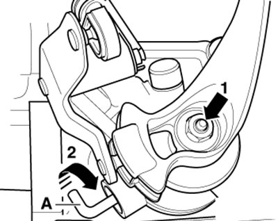
4.34. Fixing the gear shift shaft
35. Remove the sound insulation under the engine compartment (see Chapter 11), place a container under the manual transmission to collect the oil and remove the plug (1 in the illustration) drain plug and fork axle (2). Allow the oil to drain, install the drain plug and fork axle with a new sealing ring. Tighten the axle mounting bolt to 25 Nm and the plug to 30 Nm.
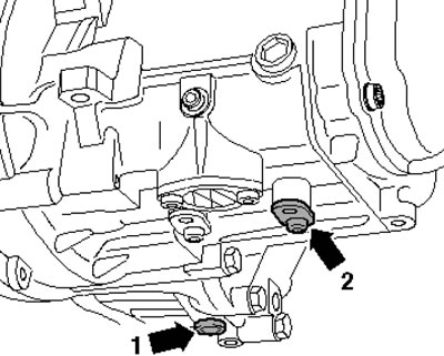
4.35. Drain plug (1) and shift fork axle (2)
36. Return the corner lever to its original position and install the sound insulation.
37. With the air cleaner removed, remove the reversing light assembly (1 in the illustration), insert a hose with a funnel into its installation hole and fill in the required volume of oil (see Specifications).
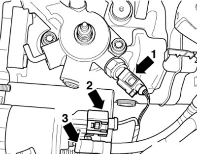
4.37. Connections of 5-speed manual transmission
Note: Use a hose approximately 60 cm long and with an outside diameter of 10 mm.
38. Tighten the reversing light D/W to 20 Nm, check the gearshift mechanism for proper operation and install the air cleaner.
Oil for 6-speed manual transmission, angular gear, Haldex clutch and rear differential
39. Raise the vehicle so that it is level.
40. When checking the oil level of the manual transmission and angular gear, remove the soundproofing panels under the engine compartment (see Chapter 11). To provide access to the filler plug of the angular transmission, unscrew the bolts (1 in the illustration) and remove the heat-protective cover (A, if available) right drive shaft (C), and on models with an independent heater - additionally separate the coolant pipes (B) from the engine (2) and the double screws on the angular transmission.
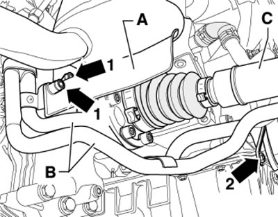
4.40. Bolts (1) of the casing (A) of the drive shaft (C) and fasteners (2) of the coolant pipes (B) on the example of a model with a manual transmission
41. Unscrew the filler plug of the manual transmission, angular gear, Haldex clutch or rear differential (see illustrations) and insert a wire bent at a right angle into it. Remove the wire - the oil should be at the level of the lower edge of the filler hole (on the bend of the wire). For the Haldex coupling, it is permissible for the fluid level to be no more than 3 mm below the lower edge of the filler hole. When checking the Haldex clutch oil, it is essential that its temperature is between 20 and 40°C. A diagnostic tool connected via the DLC connector (see Chapter 5).
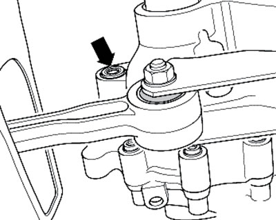
4.41a. Check and filler plug for manual transmission 0AJ
Material is available on the website: skodabook
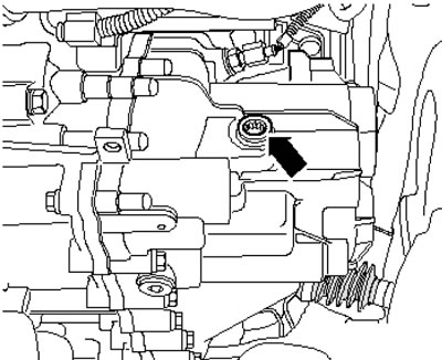
4.41b. Check and filler plug for manual transmission 02Q
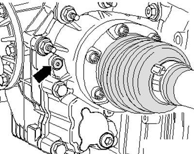
4.41s. Angular gear filler plug
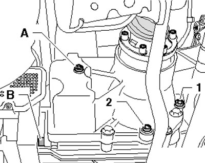
4.41d. Plugs of the inspection and filler (1 and A) and drain (2 and B) holes of the rear differential and Haldex coupling, respectively
42. If necessary, add oil through the filler hole. Since it is difficult to fill the Haldex coupling, rear differential or angular gear from under the vehicle, it is recommended to screw an adapter into the inspection and filling hole (And in illustration 4.42a) with the elbow (B) and connect the filling device VAS6291 with valve to it (arrow in illustration 4.42b) and a container with oil. Holding the container with oil above the filler hole, open the valve and let the oil drain. When the oil stops flowing and its level is above the filler hole, place a container under it to collect the oil, close the valve, disconnect the hose from the adapters and drain the remaining oil into the container to collect the oil. Remove the adapters.
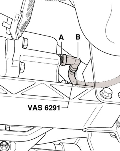
4.42a. Adapters for the VAS6291 device in the inspection and filling hole of the Haldex coupling
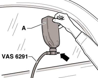
4.42b. Tool VAS6291
43. After filling the angular transmission or manual transmission 0AJ, tighten its old plug, start the engine and let the transmission run for 2 minutes at idle speed. Then turn off the engine and check the oil level again. Add more oil if necessary.
44. Finally, thoroughly clean the relevant unit if it has been exposed to oil and tighten the filler plug to the torque specified in the Specifications. For the angular gear and rear differential use a new plug, and for the 02Q manual transmission use a new plug seal. For the Haldex coupling, use a new plug with a new seal.
45. Install the remaining parts in place.
DSG transmission fluid
46. Checking the fluid level of the 6-speed DSG is done when replacing it (see Section 21).
47. The 7-speed DSG has two areas that use different fluids. Both of these fluids are filled for the life of the transmission and do not require checking or level adjustment. Replacing the fluid in the gear area is described in Chapter 7.