



2.0-liter gasoline engines of car Skoda Kodiaq 1

2.0L Petrol Engine Specifications
Main technical characteristics Letter designations CZPA Compliance with toxicity standards Euro 6 Engine displacement l 2.0 Power kW at rpm 132/3900-6000 Torque Nm at rpm 320/1500-3940 Cylinder diameter 0, mm 82,5...
Main technical characteristics Letter designations CZPA Compliance with toxicity standards Euro 6 Engine displacement l 2.0 Power kW at rpm 132/3900-6000 Torque Nm at rpm 320/1500-3940 Cylinder diameter 0, mm 82,5...

Maintenance — compression check
1. Remove the engine cover. 2. Disconnect the wiring harness connectors from the ignition coils (1, 2, 3, 4). Loosen the ground wire fasteners (arrows). Then, remove the bolt securing each ignition coil to remove it...
1. Remove the engine cover. 2. Disconnect the wiring harness connectors from the ignition coils (1, 2, 3, 4). Loosen the ground wire fasteners (arrows). Then, remove the bolt securing each ignition coil to remove it...

Attachment drive belt
1. Attachment drive belt; 2. Attachment drive belt tensioner; 3. Fastening bolt, tightening torque 8 Nm + 450; 4. Fastening bolt, tightening torque 150 Nm + 90 degrees; 5. Sealing ring; 6. Crankshaft pulley (vibration...
1. Attachment drive belt; 2. Attachment drive belt tensioner; 3. Fastening bolt, tightening torque 8 Nm + 450; 4. Fastening bolt, tightening torque 150 Nm + 90 degrees; 5. Sealing ring; 6. Crankshaft pulley (vibration...

Removal and installation a poly V-belt
Removal Attention: Installing the old belt the other way around may damage it! Before removing, mark the direction of belt movement with chalk or a felt-tip pen. 1. To loosen the tension of the poly V-belt, turn the...
Removal Attention: Installing the old belt the other way around may damage it! Before removing, mark the direction of belt movement with chalk or a felt-tip pen. 1. To loosen the tension of the poly V-belt, turn the...

Removal and installation the poly V-belt tensioner
Removal 1. Remove the poly V-belt of the accessory drive ( for more details, see the relevant section above ). 2. Unscrew the mounting bolts (arrows) shown in the figure below, then pull towards you and remove the...
Removal 1. Remove the poly V-belt of the accessory drive ( for more details, see the relevant section above ). 2. Unscrew the mounting bolts (arrows) shown in the figure below, then pull towards you and remove the...

Gas distribution mechanism drive chain cover
General appearance 1. Mounting bolt, tightening torque during installation 4 Nm + tighten additionally at an angle of 45°; 2. Exhaust camshaft oil control valve; 3. Sealing cuffs; 4. Upper timing chain cover; 5. Gasket;...
General appearance 1. Mounting bolt, tightening torque during installation 4 Nm + tighten additionally at an angle of 45°; 2. Exhaust camshaft oil control valve; 3. Sealing cuffs; 4. Upper timing chain cover; 5. Gasket;...

Upper timing chain cover
Removal and installation Removal Note: The engine must be cold. 1. Release residual pressure from the cooling system by opening the expansion tank cap shown in the figure below. 2. Remove the upper decorative engine...
Removal and installation Removal Note: The engine must be cold. 1. Release residual pressure from the cooling system by opening the expansion tank cap shown in the figure below. 2. Remove the upper decorative engine...

Lower timing chain cover
Removal and installation Removal 1. Remove the right front wheel arch liner (for more details, see the corresponding section in the chapter Body ). 2. Remove the powertrain support assembly. 3. Remove the accessory...
Removal and installation Removal 1. Remove the right front wheel arch liner (for more details, see the corresponding section in the chapter Body ). 2. Remove the powertrain support assembly. 3. Remove the accessory...

Timing chain — removal
1. Timing chain tensioner; 2. Mounting bolt, tightening torque during installation: 4 Nm + 90 degrees; 3. Guide pin, tightening torque 20 Nm; 4. Mounting bolt; 5. Bushing; 6. Phase shifter control valve, tightening...
1. Timing chain tensioner; 2. Mounting bolt, tightening torque during installation: 4 Nm + 90 degrees; 3. Guide pin, tightening torque 20 Nm; 4. Mounting bolt; 5. Bushing; 6. Phase shifter control valve, tightening...
Timing chain installation
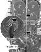
1. Check and ensure that the crankshaft is set to the TDC position of the piston of the first cylinder. The marks (arrows) should be opposite each other, as shown in the figure below. 2. Apply a mark on the cylinder...
1. Check and ensure that the crankshaft is set to the TDC position of the piston of the first cylinder. The marks (arrows) should be opposite each other, as shown in the figure below. 2. Apply a mark on the cylinder...

Cylinder head
1. Mounting pin; 2. Cylinder head gasket; 3. Cylinder head assembly; 4. Mounting screw; 5. Thermal insulation coating; 6. Fastening screw, tightening torque during installation 9 Nm; 7. Fastening screw, tightening...
1. Mounting pin; 2. Cylinder head gasket; 3. Cylinder head assembly; 4. Mounting screw; 5. Thermal insulation coating; 6. Fastening screw, tightening torque during installation 9 Nm; 7. Fastening screw, tightening...

Valve mechanism
General appearance 1. Exhaust valve; 2. Cylinder head; 3. Valve stem seal; 4. Valve spring; 5. Hydraulic compensator; 6. Spring washer; 7. Rusks; 8. Locking pin; 9. Roller pusher; 10. Exhaust camshaft; 11. Cylinder head...
General appearance 1. Exhaust valve; 2. Cylinder head; 3. Valve stem seal; 4. Valve spring; 5. Hydraulic compensator; 6. Spring washer; 7. Rusks; 8. Locking pin; 9. Roller pusher; 10. Exhaust camshaft; 11. Cylinder head...

Oil separator and vacuum pump
General appearance 1. Cylinder head assembly; 2. Sealing ring; 3. Camshaft adjustment setting element (exhaust camshaft); 4. Fastening screw, tightening torque during installation 5 Nm; 5. Ball pin, tightening torque...
General appearance 1. Cylinder head assembly; 2. Sealing ring; 3. Camshaft adjustment setting element (exhaust camshaft); 4. Fastening screw, tightening torque during installation 5 Nm; 5. Ball pin, tightening torque...

Valve sizes
Size Inlet valve Exhaust valve ∅ a mm 32.10+0.10 28.0+0.10 ∅ b mm 5.98+0.10 5.96+0.10 c mm 105.0+0.20 102.9+0.20 α • 45 45
Size Inlet valve Exhaust valve ∅ a mm 32.10+0.10 28.0+0.10 ∅ b mm 5.98+0.10 5.96+0.10 c mm 105.0+0.20 102.9+0.20 α • 45 45

Crank mechanism
Connecting rod and piston group General appearance 1. Connecting rod cover mounting bolts, tightening torque during installation: 45 Nm + additional tightening by an angle of 90°; 2. Connecting rod cover; 3. Connecting...
Connecting rod and piston group General appearance 1. Connecting rod cover mounting bolts, tightening torque during installation: 45 Nm + additional tightening by an angle of 90°; 2. Connecting rod cover; 3. Connecting...

Checking the dimensions of pistons and cylinders
Checking the piston ring gap Insert the ring from the top into the cylinder and then slide it to the bottom of the cylinder so that it is positioned approximately 15 mm from the bottom edge of the cylinder (the sides of...
Checking the piston ring gap Insert the ring from the top into the cylinder and then slide it to the bottom of the cylinder so that it is positioned approximately 15 mm from the bottom edge of the cylinder (the sides of...

Crankshaft — tightening torques
Tightening torques and tightening sequence for crankshaft main bearing bolts After disassembly, it is always necessary to replace the crankshaft main bearing cap bolts. Tighten the main bearing cap bolts in the sequence...
Tightening torques and tightening sequence for crankshaft main bearing bolts After disassembly, it is always necessary to replace the crankshaft main bearing cap bolts. Tighten the main bearing cap bolts in the sequence...
This section is available on russian, bulgarian, belarusian, ukrainian, serbian, croatian, romanian, polish, slovak, hungarian
Read similar sections on other Skoda models
➧ Power unit: Petrol engines Skoda Rapid 1 (2012-2022)
➧ Power unit: Petrol engines 1.4 l Skoda Superb 2 (2008-2015)
➧ Power unit: Petrol engine 1.4 l Skoda Yeti (2009-2017)
➧ Power unit: Petrol engine 1.6 l Skoda Felicia (1994-2001)
Link to this section in various formats
TEXTHTMLBB Code
- General information
- User manual
- Controls and instruments
- Maintenance
- Power unit
- Petrol engine 1.4 l
- Petrol engine 2.0 l
- Diesel engine 2.0 l
- Fuel and control (petrol)
- Fuel and control (diesel)
- Cooling system (petrol 1.4 l)
- Cooling system (petrol 2.0 l)
- Cooling system (diesel 2.0 l)
- Lubrication system (petrol)
- Lubrication system (diesel)
- Intake and exhaust (petrol 1.4 l)
- Intake and exhaust (petrol 2.0 l)
- Intake and exhaust (diesel 2.0 l)
- Transmission
- Clutch
- Manual gearbox
- Automatic gearbox
- Drive shafts
- Chassis (running gear)
- Front suspension
- Rear suspension
- Wheels and tires
- Brake system
- Steering system
- Body and interior
- Exterior (external elements)
- Interior (internal elements)
- Doors, locks and windows
- Heating and air conditioning
- Security systems
- Electrical equipment
- Power devices
- Equipment and devices
- Electrical circuits
- Electrical circuits (petrol 2.0 l)
- Electrical circuits (halogen headlights)
- Electrical circuits (LED headlights)
- Electrical circuits (Climatronic)