



The braking system of car Skoda Kodiaq 1

Brake system — technical data and description
Main technical characteristics Brake master cylinder and brake booster Brake master cylinder ∅, mm 23,8 Brake booster (left-hand drive car) ∅, inches 11 Brake booster (right-hand drive vehicles) ∅, inches 8/8 Front...
Main technical characteristics Brake master cylinder and brake booster Brake master cylinder ∅, mm 23,8 Brake booster (left-hand drive car) ∅, inches 11 Brake booster (right-hand drive vehicles) ∅, inches 8/8 Front...

Front brake components
Components 1. Mudguard; 2. Mounting bolt, installation tightening torque: 12 Nm; 3. Brake disc; 4. Mounting bolt, installation tightening torque: 8 Nm; 5. Brake caliper support bracket assembly; 6. Brake pads; 7. Brake...
Components 1. Mudguard; 2. Mounting bolt, installation tightening torque: 12 Nm; 3. Brake disc; 4. Mounting bolt, installation tightening torque: 8 Nm; 5. Brake caliper support bracket assembly; 6. Brake pads; 7. Brake...
Front brakes — system description
The disc brake mechanism consists of the following components: Disc brake pads: apply the mechanical output force from the hydraulic brake calipers to the friction surfaces of the brake rotors. Disc brakes use...
The disc brake mechanism consists of the following components: Disc brake pads: apply the mechanical output force from the hydraulic brake calipers to the friction surfaces of the brake rotors. Disc brakes use...

Replacing the front brake pads
Note: Brake pads must be replaced on both sides of the vehicle's front axle. Caution: Do not use brake fluid that is not recommended by the manufacturer. Also, do not reuse brake fluid after draining. Do not use brake...
Note: Brake pads must be replaced on both sides of the vehicle's front axle. Caution: Do not use brake fluid that is not recommended by the manufacturer. Also, do not reuse brake fluid after draining. Do not use brake...

Removal and installation the front brake caliper
Removal Note: The following work is performed only when replacing the brake caliper and precedes subsequent repair work. Note: Do not use power or pneumatic tools to loosen or tighten the brake caliper guide pin bolts....
Removal Note: The following work is performed only when replacing the brake caliper and precedes subsequent repair work. Note: Do not use power or pneumatic tools to loosen or tighten the brake caliper guide pin bolts....

Front brake disc — removal and installation
1. Remove the front wheel assembly. 2. Remove the brake pads as an assembly ( for more details, see the relevant section in this chapter ). 3. Unscrew the brake caliper mounting screws. 4. Remove the screw (arrow) of...
1. Remove the front wheel assembly. 2. Remove the brake pads as an assembly ( for more details, see the relevant section in this chapter ). 3. Unscrew the brake caliper mounting screws. 4. Remove the screw (arrow) of...

Checking the technical condition of the front brake components
Checking the technical condition of brake pads 1. It is necessary to regularly inspect and check the technical condition of the brake pads and, using a suitable measuring tool, measure the thickness of the friction...
Checking the technical condition of brake pads 1. It is necessary to regularly inspect and check the technical condition of the brake pads and, using a suitable measuring tool, measure the thickness of the friction...
Break-in of brake pads and discs
Attention: Conduct test drives in safe conditions and observing all traffic rules. Do not attempt any maneuvers that involve the risk of losing control of the vehicle. Failure to follow these precautions could result in...
Attention: Conduct test drives in safe conditions and observing all traffic rules. Do not attempt any maneuvers that involve the risk of losing control of the vehicle. Failure to follow these precautions could result in...
Road test of the vehicle's braking system
Preliminary examinations 1. Inspect accessible and visible components of the brake system for damage and/or leaks that would prevent the vehicle from being driven until the next inspection. 2. Check the fluid level in...
Preliminary examinations 1. Inspect accessible and visible components of the brake system for damage and/or leaks that would prevent the vehicle from being driven until the next inspection. 2. Check the fluid level in...
Checking the brake caliper mounting bracket
1. Check the brake fluid level in the expansion tank of the master brake cylinder. If the brake fluid level is halfway between the lower and upper marks, no further operations with the brake fluid are required. If the...
1. Check the brake fluid level in the expansion tank of the master brake cylinder. If the brake fluid level is halfway between the lower and upper marks, no further operations with the brake fluid are required. If the...
Grinding brake discs (if permitted by the manufacturer)
Note: Brake discs do not require resurfacing as part of normal brake system maintenance. Do not regrind brake discs to correct the following defects: Extraneous noises in the brake mechanisms. Uneven and/or increased...
Note: Brake discs do not require resurfacing as part of normal brake system maintenance. Do not regrind brake discs to correct the following defects: Extraneous noises in the brake mechanisms. Uneven and/or increased...

Rear brake components
Components 1. Mudguard; 2. Torx mounting bolt, installation tightening torque: 12 Nm; 3. Brake disc; 4. Tone mounting bolt, installation tightening torque: 8 Nm; 5. Brake caliper; 6. Multi-point head mounting bolt,...
Components 1. Mudguard; 2. Torx mounting bolt, installation tightening torque: 12 Nm; 3. Brake disc; 4. Tone mounting bolt, installation tightening torque: 8 Nm; 5. Brake caliper; 6. Multi-point head mounting bolt,...

Replacing rear brake pads — removal and installation
Note: Brake pads must be replaced on both sides of the vehicle's front axle. Caution: Do not use brake fluid that is not recommended by the manufacturer. Also, do not reuse brake fluid after draining. Do not use brake...
Note: Brake pads must be replaced on both sides of the vehicle's front axle. Caution: Do not use brake fluid that is not recommended by the manufacturer. Also, do not reuse brake fluid after draining. Do not use brake...

Rear Brake Caliper — removal and installation
Note: The following work is performed only when replacing the brake caliper and precedes subsequent repair work. Note: Do not use power or pneumatic tools to loosen or tighten the brake caliper guide pin bolts. When...
Note: The following work is performed only when replacing the brake caliper and precedes subsequent repair work. Note: Do not use power or pneumatic tools to loosen or tighten the brake caliper guide pin bolts. When...
Hydraulic brake drive — description
Hydraulic brake system The hydraulic brake system consists of the following components: Master Cylinder Reservoir: Contains a supply of brake fluid for the hydraulic brake system. Master cylinder of a hydraulic brake...
Hydraulic brake system The hydraulic brake system consists of the following components: Master Cylinder Reservoir: Contains a supply of brake fluid for the hydraulic brake system. Master cylinder of a hydraulic brake...

Brake pedal components
Components 1. Brake pedal mounting bracket; 2. Fastening nut, tightening torque 25 Nm; 3. Retainer; 4. Bushing; 5. Overlay; 6. Brake pedal; 7. Support hinge; 8. Support; 9. Pedal axle.
Components 1. Brake pedal mounting bracket; 2. Fastening nut, tightening torque 25 Nm; 3. Retainer; 4. Bushing; 5. Overlay; 6. Brake pedal; 7. Support hinge; 8. Support; 9. Pedal axle.

Brake pedal support bracket — removal and installation
Removal 1. Remove the side cover of the instrument panel on the driver's side (for more details, see the corresponding section in the chapter " Body "). 2. Remove the floor covering from the driver's side. 3. Remove the...
Removal 1. Remove the side cover of the instrument panel on the driver's side (for more details, see the corresponding section in the chapter " Body "). 2. Remove the floor covering from the driver's side. 3. Remove the...

Disconnecting the brake pedal from the brake booster rod
Note: Required special tools, measuring instruments and auxiliary equipment Puller "T10159". 1. Remove the driver's side footwell trim. 2. Remove the fuse box cover in the front panel, bottom left. 3. Remove the...
Note: Required special tools, measuring instruments and auxiliary equipment Puller "T10159". 1. Remove the driver's side footwell trim. 2. Remove the fuse box cover in the front panel, bottom left. 3. Remove the...

Disassembling and assembling the front brake caliper
Disassembly 1. Use compressed air to push the piston out of the disc brake caliper. Note: Place a wooden strip in the hole to avoid damaging the piston. 2. Remove the sealing ring using a plastic wedge (3409). Note:...
Disassembly 1. Use compressed air to push the piston out of the disc brake caliper. Note: Place a wooden strip in the hole to avoid damaging the piston. 2. Remove the sealing ring using a plastic wedge (3409). Note:...

Replacing the rear brake caliper boot — disassembly and assembly
Disassembly Note: There is no need to remove the brake caliper assembly to replace the boot. Do not disconnect the brake hose from the brake caliper. Note: The piston must be moved away from the disc. It is necessary to...
Disassembly Note: There is no need to remove the brake caliper assembly to replace the boot. Do not disconnect the brake hose from the brake caliper. Note: The piston must be moved away from the disc. It is necessary to...

Brake pipe repair
Service Manual 1. Unscrew the corresponding brake line on the disc brake caliper or on the wheel brake cylinder; leaking brake fluid must be captured and disposed of in accordance with the regulations. 2. Using a pipe...
Service Manual 1. Unscrew the corresponding brake line on the disc brake caliper or on the wheel brake cylinder; leaking brake fluid must be captured and disposed of in accordance with the regulations. 2. Using a pipe...
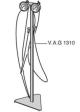
Checking the tightness of the master brake cylinder
1. Unscrew the air release valve on one of the front calipers of the disc wheel brake mechanism. 2. Connect and bleed the pressure gauge of the test device (VAG 1310) or (VAG 1310 A). 3. Apply pressure to the brake...
1. Unscrew the air release valve on one of the front calipers of the disc wheel brake mechanism. 2. Connect and bleed the pressure gauge of the test device (VAG 1310) or (VAG 1310 A). 3. Apply pressure to the brake...

Bleeding (bleeding) the brake hydraulic system
Note: Bleeding the brake systems of cars with ABS is carried out in the same way as for cars without such a system. Brake fluid is poisonous. In addition, due to the corrosive effect of brake fluid, it should not be...
Note: Bleeding the brake systems of cars with ABS is carried out in the same way as for cars without such a system. Brake fluid is poisonous. In addition, due to the corrosive effect of brake fluid, it should not be...

Brake master cylinder — removal and installation
Caution: Do not use brake fluid that is not recommended by the manufacturer. Also, do not reuse brake fluid after draining. Do not use brake fluid that has been stored for a long time in a non-sealed container, as the...
Caution: Do not use brake fluid that is not recommended by the manufacturer. Also, do not reuse brake fluid after draining. Do not use brake fluid that has been stored for a long time in a non-sealed container, as the...

Vacuum booster assembly
Removal and installation 1. Press the brake pedal to equalize the pressure in the brake booster. 2. Remove the brake master cylinder assembly ( for more details, see the relevant section in this chapter ). 3. Disconnect...
Removal and installation 1. Press the brake pedal to equalize the pressure in the brake booster. 2. Remove the brake master cylinder assembly ( for more details, see the relevant section in this chapter ). 3. Disconnect...
Checking the brake booster
Note: Engine temperature, accessory load, and altitude will affect engine vacuum. The vacuum value will decrease by approximately 2.7 kPa for every 305 m of elevation above sea level. 1. Disconnect the engine vacuum...
Note: Engine temperature, accessory load, and altitude will affect engine vacuum. The vacuum value will decrease by approximately 2.7 kPa for every 305 m of elevation above sea level. 1. Disconnect the engine vacuum...

Parking brake servo motor — removal and installation
Removal Caution: Turn off the ignition and wait at least 30 seconds before disconnecting the wiring harness connector. 1. Disconnect the wiring harness connector (2) shown in the figure below from the parking brake...
Removal Caution: Turn off the ignition and wait at least 30 seconds before disconnecting the wiring harness connector. 1. Disconnect the wiring harness connector (2) shown in the figure below from the parking brake...

Anti-lock braking system
Components 1. Electronic control unit of the ABS/ESC system; 2. Hydraulic control unit of the ABS system; 3. Mounting screw; 4. Brake pipe (to the rear right brake mechanism), tightening torque of the coupling nut 14...
Components 1. Electronic control unit of the ABS/ESC system; 2. Hydraulic control unit of the ABS system; 3. Mounting screw; 4. Brake pipe (to the rear right brake mechanism), tightening torque of the coupling nut 14...
Description of braking systems
Brake system warning indicator The brake system warning indicator comes on when the following occurs: The indicators on the instrument panel are checked. The brake system warning indicator lights up for 5 seconds. The...
Brake system warning indicator The brake system warning indicator comes on when the following occurs: The indicators on the instrument panel are checked. The brake system warning indicator lights up for 5 seconds. The...
Anti-lock braking system repair instructions
1. Before repairing the anti-lock braking system, determine the cause of the malfunction using the "Guided Fault Finding" tester -VAS 5051-. 2. With the ignition off, disconnect the ground wire from the battery. 3. When...
1. Before repairing the anti-lock braking system, determine the cause of the malfunction using the "Guided Fault Finding" tester -VAS 5051-. 2. With the ignition off, disconnect the ground wire from the battery. 3. When...
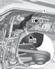
Electronic control unit and hydraulic module of the ABS system — removal and installation
Removal Caution: When connecting or disconnecting brake lines, be extremely careful not to bend or twist them. 1. Read and write down the unique code of the hydraulic control unit of the anti-lock brake system. 2....
Removal Caution: When connecting or disconnecting brake lines, be extremely careful not to bend or twist them. 1. Read and write down the unique code of the hydraulic control unit of the anti-lock brake system. 2....
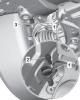
Front wheel speed sensor
Removal and installation 1. Raise the entire vehicle. 2. Disconnect the wiring harness connector (3) from the left wheel speed sensor G45/G47, as shown in the figure below. 3. Unscrew the fastening screw (2). 4. Remove...
Removal and installation 1. Raise the entire vehicle. 2. Disconnect the wiring harness connector (3) from the left wheel speed sensor G45/G47, as shown in the figure below. 3. Unscrew the fastening screw (2). 4. Remove...

Rear wheel speed sensor
Removal and installation 1. Raise the entire vehicle. 2. Disconnect the wiring harness connector (3) from the rear wheel speed sensor. 3. Unscrew the fastening screw (2) shown in the figure below. 4. Remove the rear...
Removal and installation 1. Raise the entire vehicle. 2. Disconnect the wiring harness connector (3) from the rear wheel speed sensor. 3. Unscrew the fastening screw (2) shown in the figure below. 4. Remove the rear...
Possible malfunctions, causes and solutions
Possible malfunction Cause Solution Brake pedal feel is low or pedal travel is soft Brake fluid leaks Locate the leak and fix it Air in the hydraulic drive of the brake system Bleed the brake system The piston seals in...
Possible malfunction Cause Solution Brake pedal feel is low or pedal travel is soft Brake fluid leaks Locate the leak and fix it Air in the hydraulic drive of the brake system Bleed the brake system The piston seals in...
This section is available on russian, bulgarian, belarusian, ukrainian, serbian, croatian, romanian, polish, slovak, hungarian
Read similar sections on other Skoda models
➧ Chassis (running gear): Brake system Skoda Fabia 1 (1999-2007)
➧ Chassis (running gear): Brake system Skoda Rapid 1 (2012-2022)
➧ Chassis (running gear): Brake system Skoda Octavia 1 (1996-2004)
➧ Chassis (running gear): Brake system Skoda Superb 2 (2008-2015)
➧ Chassis (running gear): Brake system Skoda Yeti (2009-2017)
➧ Chassis (running gear): Brake system Skoda Felicia (1994-2001)
Link to this section in various formats
TEXTHTMLBB Code
- General information
- User manual
- Controls and instruments
- Maintenance
- Power unit
- Petrol engine 1.4 l
- Petrol engine 2.0 l
- Diesel engine 2.0 l
- Fuel and control (petrol)
- Fuel and control (diesel)
- Cooling system (petrol 1.4 l)
- Cooling system (petrol 2.0 l)
- Cooling system (diesel 2.0 l)
- Lubrication system (petrol)
- Lubrication system (diesel)
- Intake and exhaust (petrol 1.4 l)
- Intake and exhaust (petrol 2.0 l)
- Intake and exhaust (diesel 2.0 l)
- Transmission
- Clutch
- Manual gearbox
- Automatic gearbox
- Drive shafts
- Chassis (running gear)
- Front suspension
- Rear suspension
- Wheels and tires
- Brake system
- Steering system
- Body and interior
- Exterior (external elements)
- Interior (internal elements)
- Doors, locks and windows
- Heating and air conditioning
- Security systems
- Electrical equipment
- Power devices
- Equipment and devices
- Electrical circuits
- Electrical circuits (petrol 2.0 l)
- Electrical circuits (halogen headlights)
- Electrical circuits (LED headlights)
- Electrical circuits (Climatronic)