



Instrument panel, processor, alarms, fuel pump
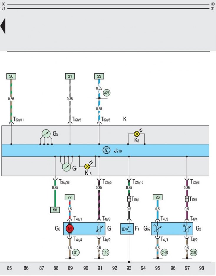
F1 – hydraulically operated oil pressure switch-sensor;
G – fuel level indicator measuring device;
G1 – fuel level indicator;
G2 – temperature indicator sensor;coolant;
G5 – tachometer;
G6 – fuel pump;
G62 – coolant temperature sensor;
J218 – Instrument cluster processor;
K – instrument panel;
K3 – oil pressure drop alarm;
K16 – low fuel emergency indicator;
T4a – four-pin plug connector, on the coolant temperature gauge sensor;
T10f – ten-pin plug connector, in the cable channel on the left (black);
T32a – 32-pin plug connector, on the instrument panel (blue);
T32b – 32-pin plug connector, on the instrument panel (green);
81 – ground connection in the wiring harness behind the instrument panel;
110 – ground connection in the wiring harness behind the instrument panel;
250 – ground connection in the engine wiring harness;
A27 - connection (vehicle speed signal) in the wiring harness behind the instrument panel on the left (only for vehicles with central door locking system);
D142 – connection in the engine wiring harness
The structure of the basic diagrams of electrical equipment is located here →
Symbols found in wiring diagrams are here →
Explanations of the symbols found on the electrical diagrams are located here →