
Motronic control unit, throttle, speedometer sensor, ignition
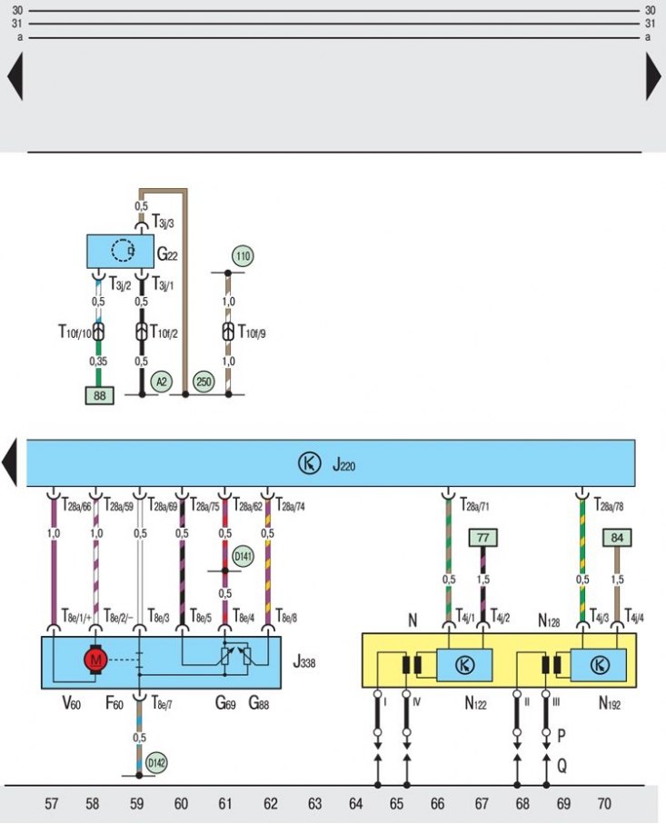
F60 - idle limit switch;
G22 - speedometer sensor;
G69 - throttle potentiometer;
G88 - Throttle valve setting element potentiometer for idle speed control;
J220 - system control unit "Motronic";
J338 - throttle control unit;
N - ignition coil 1;
N - 122 terminal powerful cascade 1;
N - 128 ignition coil 2;
N - 192 terminal powerful cascade 2;
P - tips of high voltage wires in the ignition system;
Q - spark plugs;
T3j - three-pin plug connector on the speed sensor;
T4j - four-pin plug connector on the final powerful stage;
T8e - eight-pin plug connector on the throttle control unit;
T10f - 10-pin plug connector in cable duct on the left (black);
T28a - 28-pin connector on the control unit "Motronic";
V60 - Throttle adjuster;
110 - connection to "mass" in the wiring harness behind the instrument panel;
250 - connection on "mass" in the engine wiring harness;
A2 - connection with positive pole (15) in the wiring harness behind the instrument panel;
D141 - connection (5V) in the engine wiring harness;
D142 - Connection in engine wiring harness
The structure of circuit diagrams of electrical equipment is located here →
Symbols found in circuit diagrams are here →
Explanations for the symbols found in the wiring diagrams are here →