
Assembly diagram - shifting drive gear
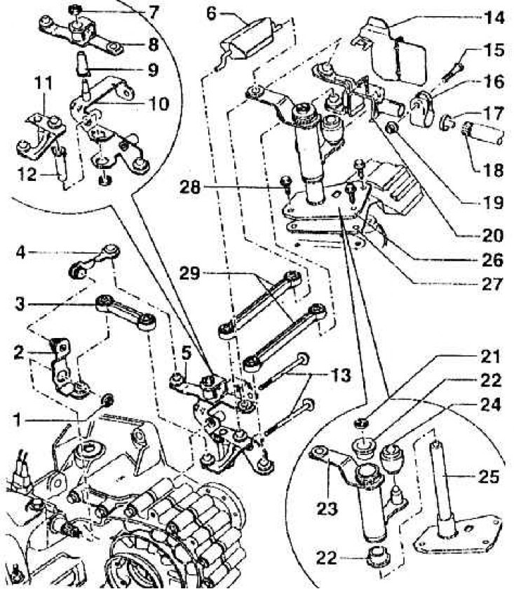
1 - self-locking nut, 25 Nm (gear lever to gearbox); 2 - gearshift lever (sits well in only one position on the shift shaft); 3 - rail; 4 - a rod of a fork of a gear change - ahead; 5 - bracket (assembled); 6 – a rod of a fork of a gear change with a balancing small weight; 7 - safety washer; 8 - intermediate lever; 9 - bearing sleeve (insert from below into the intermediate lever); 10 - bracket; 11 – the directing lever of switching; 12 - bearing sleeve (put it on top of the bracket); 13 - hex head screw M8x98, 25 Nm; 14 - screen (put on the selective gearshift control lever); 15 - hex head screw M8x28; 16 - clamping bracket; 17 - cork; 18 – a rod of a fork of a gear change; 19 - hex nut with shoulder, self-locking, 20 Nm; 20 – the lever of preselective control of a gear change; 21 - safety washer; 22 - bearing sleeve; 23 – the directing lever of switching; 24 - ball bushing; 25 - support bracket; 26 - support bracket (with guide lever); 27 - screen; 28 - 25 Nm; 29 - slats