
Assembly Diagram - Drive Case/Shift Lever
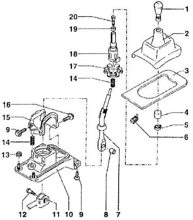
1 – a spherical head of the lever of a gear change (when disassembling, remove the cover, position 2); 2 - casing with frame (remove the frames by disassembling, at the same time check the ball head of the gear lever, position 1; detaching the casing from the head of the gear lever; 3 - noise-absorbing cover; 4 - connecting piece (connects the casing to the head of the gear lever); 5 - hose clamp (for attaching the shift lever head to the shift lever); 6 - holding clamps; 7 - gearshift lever (after assembling the gearshift drive); 8 - spacer sleeve; 9 - screw with shoulder M8x20, 25 Nm; 10 – the case of the mechanism of a gear change; 11 – a rod of a fork of a gear change (after assembling the gearshift drive to be adjusted); 12 - 20 Nm; 13 - self-locking nut; 14 - compression spring; 15 - emphasis (after assembling the gearshift drive to be adjusted); 16 - precision bolt M8x20, 25 Nm; 17 - ball bearing; 18 - sleeve; 19 - shock absorber; 20 - 15 Nm;