Attention. Set the steering wheel to the straight ahead position. Make sure that the steering wheel and front steering wheels do not turn during work.
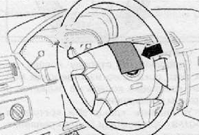
1. Fix the steering wheel to the straight-ahead position using special adhesive tape as shown in the figure below.
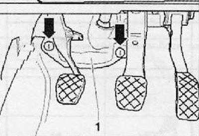
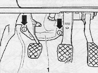
2. Loosen the plastic nuts (arrows) and remove the lower trim panel (1), shown in the figure below.
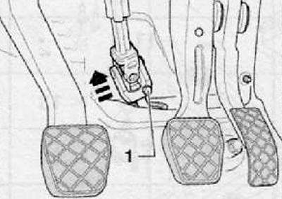
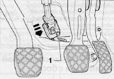
3. Unscrew the fastening bolt (1), connecting the steering column shaft to the steering shaft through the universal joint as shown in the figure below.
4. Disconnect the universal joint from the steering shaft by moving it in the direction of the arrow as shown in the figure below.
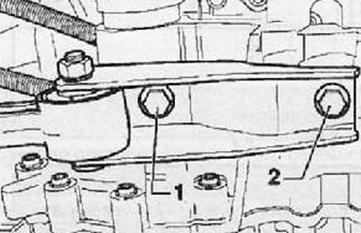
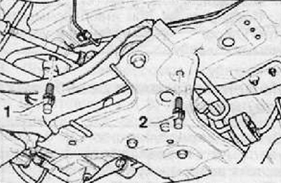
5. Unscrew the fastening bolts (2) And (3) oscillator as shown in the figure below.
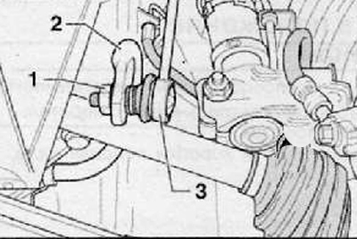
6. Loosen the fastening nut (1) struts to the anti-roll bar, as shown in the figure below. Perform the operation on both sides.
7. Remove the hinges of the racks (3) from anti-roll bar (2), as shown in the figure below.
8. Raise the anti-roll bar with the lugs up.
9. Put on a special support (VAG 1359/2) wooden block (1), as shown in the figure below.
10. Support the subframe assembly with a special hydraulic jack and support.
Note. Tighten the bolts securing the special tool to a maximum torque of 20 Nm.
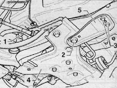
11. Unscrew the left mounting bolt (1) subframe assembly (4), as shown in the figure below. Screw a bolt from a special tool into this hole (Т10096) and tighten it with a tightening torque of 20 Nm.
12. Unscrew the right mounting bolt (2) subframe assembly (not shown in the picture below). Screw a bolt from a special tool into this hole (Т10096) and tighten it with a tightening torque of 20 Nm.
13. Unscrew the fastening bolts (3) on both sides, as shown in the figure below.
14. Unscrew the left mounting bolt (2), shown in the figure below, then remove the support (5).
15. Screw the mounting bolts into the hole (Т10486/1) and tighten them with a tightening torque of 20 Nm.
16. Unscrew the right mounting bolt (2) and remove the support (5), as shown in the figure below.
17. Screw the mounting bolts into the hole (Т10486/1) and tighten them with a tightening torque of 20 Nm.
Note. Installation is considered correct when all four mounting bolts (1 and 2) on both sides of the vehicle are replaced with special tool fixing bolts.
18. Lower the subframe assembly by about 4 cm and loosen the mounting bolts.
Note. When lowering the subframe assembly, ensure that there is clearance between the anti-roll bar and the drive shafts.
19. Slowly lower subframe assembly with engine and gearbox and hydraulic jack.
20. To install the subframe from the service position to its original position, it is necessary: to raise the subframe assembly on a hydraulic jack until it touches the body console on both sides.
21. Unscrew the left fixing bolt (1) from a special tool (Т10096), screw in and tighten the new subframe mounting bolt to the required torque, as shown in the figure below.
22. Unscrew the right fixing bolt (1) from a special tool (Т10096), screw in and tighten the new subframe mounting bolt to the required torque, as shown in the figure below.
23. Install the left support.
24. Install and tighten the bolts of the left support by hand.
25. Install and tighten with the required torque new bolts securing the left support to the subframe.
26. Tighten the bolts securing the left support to the subframe with the required tightening torque.
27. Unscrew the fastening bolts (2) from fixture (Т10486/1) (not shown in the figure below).
28. Install the right support.
29. Install and tighten the bolts of the right support by hand.
30. Install and tighten with the required torque the bolts securing the right support to the front suspension subframe assembly.
31. Tighten the bolts securing the right support to the body with the required tightening torque.
32. Remove from under the car a special hydraulic jack together with a support.
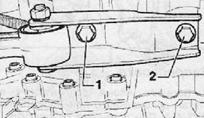
33. Install the oscillating support on the gearbox, then install and tighten the new support mounting bolts, as shown in the figure below.
Note. Install mounting bolt (1) in an elongated hole as far away from the gearbox and subframe as possible.
34. Install a soundproof coating.
35. Connect the universal joint to the steering shaft by moving it in the direction of the arrow, as shown in the figure below. Then install and tighten the connecting bolt (1).
36. Install cover (1) and tighten the plastic fastening nuts shown in the figure below by arrows.
37. Remove the latch from the steering mechanism.
38. Carry out a road test of the vehicle.
39. During a road test, check and make sure that the steering gear is installed correctly.
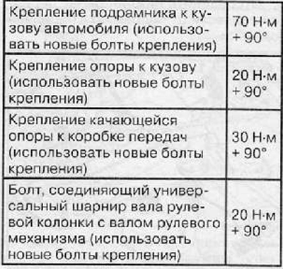
Tightening torques for threaded connections