
Earbud selection
1. To select the required connecting rod bearings, you will first need to determine the size group of the connecting rod journals of the crankshaft. To do this, measure the diameters of the connecting rod journals and, based on the measurements obtained, Specifications determine their size group (see chapter 14 for details).
2. The size group of the crankshaft journals can be determined in another way. Measure the thickness of the old bearings using a suitable micrometer, then compare the readings with those in the table below. It is preferable to still use crankshaft journal dimensions, as bearings are more difficult to measure accurately and are likely to wear out.
3. When the size group of the crankpin is known, the correct liners can be selected from the table below:
| Dimensional group of connecting rod neck | Liner thickness |
| Nominal | 1.490 mm |
| 1st repair | 1.615 mm |
| 2nd repair | 1.740 mm |
| 3rd repair | 1.865 mm |
Please note that all new liners have a manufacturing tolerance of +0.000 to -0.007 mm.
Checking the operating clearance of the connecting rod bearing
4. Be guided Chapter 18, paragraph 7. The gap can be checked in one of two ways.
5. First method (which is difficult to use without a set of calipers or expandable calipers): put the connecting rod bearing caps together with the shells in working position. Tighten the bolts for fastening the covers with a tightening force regulated specifications. Measure the inner diameter of each pair of bearings and the diameter of the corresponding crankshaft journal. The difference in diameters will be the working clearance of the connecting rod bearing.
6. Second method (more accurate): using an American product known as a Plastigage special tool (see Chapter 18, paragraphs 9-17).
Final installation
7. Note that the following procedure assumes that the cylinder liners are installed in the crankcase and clamped into position as described in Chapter 12, and that the crankshaft and main bearing caps are also in the running position. Piston/connecting rod assemblies must be attached to the crankshaft (see chapter 18).
8. Clean the back side of the liners and bearing surfaces in the connecting rods and caps. If new bearings are installed, wipe off protective grease from them.
9. Insert the bushings into their seats, making sure that the tab on each bushing fits into the notch in the connecting rod or cap. Please note that the old liners must be installed in their original places.
10. Lubricate the cylinder walls, pistons and piston rings, then place each piston/connecting rod assembly in its proper position.
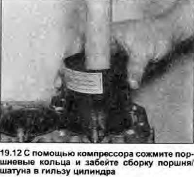
11. Starting with assembly #1, position the piston ring cuts as described in Chapter 17, then tighten the rings with a special compressor.
12. Insert the piston/connecting rod assembly into the top of the #1 cylinder liner. The arrow on the piston head or near the piston pin hole must point towards the front of the engine (priming pump side), and the oil passage on the connecting rod must face the rear of the engine. By hitting the piston head with a block of wood or a hammer handle, hammer the assembly into the sleeve (see illustration).
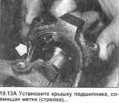
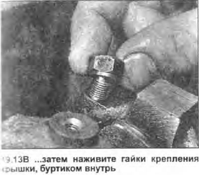
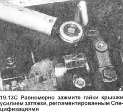
13. Make sure the bushing has not moved, then liberally lubricate the crankshaft journal and both bushings. Being careful not to scratch the inside of the cylinders, slide the piston/connecting rod assembly down onto the crankshaft crankpin. Install the connecting rod cap with bearing, orienting it correctly. Screw on the cover nuts, and evenly tighten them with a tightening torque regulated specifications (see illustrations). After that, make sure the crankshaft rotates freely, and then proceed to the next assembly.
 |  |
 |
14. Repeat the procedure for the remaining three piston/rod assemblies.
15. When all assemblies are installed, check that the crankshaft rotates freely. The new components will make rotation slightly more difficult, but these places should not be felt.