Removing
1. Remove the front suspension lower arm assembly (see relevant section in this chapter).
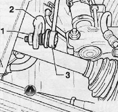
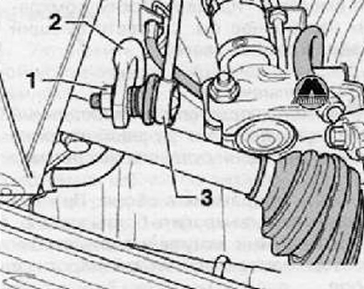
2. Loosen the fastening nuts (1) racks to the anti-roll bar on the right and left side, as shown in the figure below.
3. Pull and detach the stand (3) from anti-roll bar (2), as shown in the figure below. Repeat this operation on both sides.
4. Rotate the anti-roll bar and install with the lugs up.
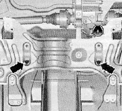
5. Unscrew the fastening bolts (arrows) and disconnect the steering gear assembly from the front suspension subframe, as shown in the figure below. Hang the steering gear using a suitable piece of wire.
6. Unscrew the mounting bolts, disconnect from the body and remove the front suspension subframe assembly, lower it together with the hydraulic jack (see the corresponding section in this chapter for more details).
Note. Do not disconnect the steering column shaft universal joint from the steering pinion shaft.
7. Remove subframe assembly. If necessary, unscrew the bolts securing the mounting clamps and remove the anti-roll bar assembly.
Installation
Note. Before finally installing the subframe mounting bolts, install and tighten the steering assembly mounting bolts to the subframe.
1. If dismantled, reinstall the anti-roll bar.
2. Install the front suspension subframe assembly with engine and gearbox on the hydraulic jack adapter.
3. Raise the hydraulic jack assembly with the subframe and bring it to the vehicle body. Temporarily install the steering gear assembly on the subframe.
4. Insert and tighten by hand the bolts of the steering mechanism to the subframe, as shown in the figure below.
5. Bring the subframe assembly until it touches the body.
Note. Check the correct installation of the steering column shaft boot on the body cross member.
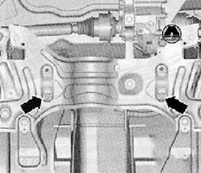
6. Tighten finally with the required tightening torque the bolts securing the steering mechanism to the subframe, as shown in the figure above.
7. Install and tighten the bolts securing the subframe to the car body (see above about it).
8. Connect to the anti-roll bar, right and left side (2), racks (3) stabilizer as shown in the figure below.
9. Install and tighten with the required tightening torque the nuts securing the struts to the anti-roll bar (1), as shown in the figure below.
10. Install the front lower control arm (for details, see the relevant section in this chapter).
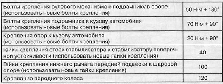
Tightening torques for threaded connections