
Company vehicles Hyundai Company vehicles Kia Company vehicles Lada Company vehicles Mazda Company vehicles Mercedes-Benz Company vehicles Opel Company vehicles Mitsubishi
English Русский
Български
Беларускі
Український
Српски
Hrvatski
Română
Polski
Slovenský
Magyar
Articles   
Bookmark Contacts Sitemap
SkodaBook.ru


Fabia Rapid Octavia Superb Kodiaq Yeti Others
Rapid 1 (2012-2022)

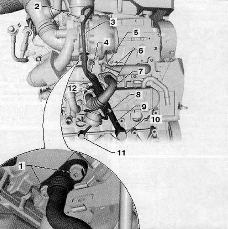
Turbocharger Oil Inlet and Outlet Pipe Assembly Diagram (1.6L TDI Engine) (Skoda Rapid NH1)

  • Main
  • Rapid
  • NH1 (2012-2022)
  • Power unit
  • Lubrication system
  • Turbocharger Oil Inlet and Outlet Pipe Assembly Diagram (1.6L TDI Engine)
0
1. Fastening bolt, tightening torque during…

1. Fastening bolt, tightening torque during installation 20 Nm
2. Fastening bolt, tightening torque during installation 22 Nm
3. Lubricating oil supply line
4. Drain lubrication line
5. Fastening bolt. Tightening torque during installation 20 Nm
6. Fastening bolt, tightening torque during installation 25 Nm
7. Connecting pipe to the EGR cooler
8. Fastening bolt, tightening torque during installation 10 Nm
9. Turbocharger support
10. Hollow connecting screw, tightening torque during installation 60 Nm
11. Hollow connecting screw, tightening torque during installation 30 Nm
12. Fastening bolt, tightening torque during installation 25 Nm
This article is available at russian, bulgarian, belarusian, ukrainian, serbian, croatian, romanian, polish, slovak, hungarian
Article verified: Anatoly Ovchinnikov
Share with friends:
◀ Previous
Skoda Rapid 1: Lubrication system
Next ►

Engine Oil Pressure Drop Sensor — Removal and Installation (1.6L TDI…
Engine Oil Cooler — Removal and Installation (1.6L TDI Engine)
Oil filter assembly with holder and engine oil cooler — removal and…
Oil filter holder (1.6L TDI engine)
Lubrication system components of the 1.6 l TDI engine in assembly
Oil pan — removal and installation (1.6L TDI engine)
Oil pump — removal and installation (1.6 l TDI engine)
Read similar articles on other Skoda models

➧ Removal and installation a turbocharger for an engine with the letter… Skoda Fabia 2 (2007-2014)
➧ Assembly diagram of the engine hood Skoda Octavia 1 (1996-2004)
➧ Starting the engine from an auxiliary power source Skoda Superb 2 (2008-2015)
➧ Engine speed sensor, Hall sensor, Radiator outlet coolant temperature… Skoda Kodiaq 1 (2016-2024)
➧ Starting the engine from an auxiliary power source Skoda Yeti (2009-2017)
➧ Layout of components in the engine compartment (air filter removed) Skoda Favorit (1987-1994)
Link to this article in various formats
Reviews and comments of visitors
No comments yet


Add two numbers: 19 + 27


Rapid 1 (2012-2022) 
  • General information
  • Faults en route
  • User manual
  • Maintenance and care
  • Power unit
  • Petrol engines
  • Diesel engines
  • Power and control system
  • Lubrication system
  • Cooling system
  • Intake and exhaust system
  • Transmission
  • Clutch
  • Mechanical gearbox
  • Automatic gearbox
  • Drive shafts
  • Chassis (running gear)
  • Front suspension
  • Rear suspension
  • Brake system
  • Steering
  • Body and interior
  • Exterior (external elements)
  • Interior (internal elements)
  • Doors, locks and windows
  • Heating and air conditioning
  • Security systems
  • Electrical equipment
  • Equipment and devices
  • Power devices
  • Electrical circuits
  • Electrical circuits (petrol)
  • Electrical circuits (diesel)
SkodaBook.ru © 2018–2026 | Mobile version | Articles on Skoda | Sitemap EN BG BY UA RS HR RO PL SK HU | Feedback | Site search | Bookmark
Fabia 1 (1999-2007) | Fabia 2 (2007-2014) | Rapid 1 (2012-2022) | Octavia 1 (1996-2004) | Octavia 3 (2013-2019) | Superb 2 (2008-2015) | Kodiaq 1 (2016-2024) | Yeti (2009-2017) | Favorit (1987-1994) | Felicia (1994-2001) |
By continuing to use the site, you agree to the use of cookies.