



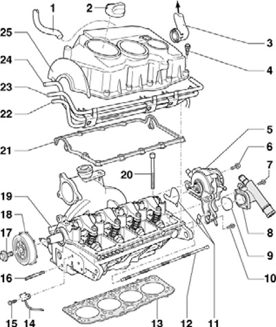
45.1 Cylinder head and cover installation details
1 Vacuum hose (from pump to brake booster)
2 Threaded plug
3 PCV Connecting Tube, to Inlet Hose
4, 7, 10 Bolt, 10 Nm
5 Twin pump
6 Bolt, 20 Nm
8 Coolant pipe flange
9 Sealing ring, subject to replacement
11 Gaskets
12 Mixing tube, pulled out with a hook
13 Head gasket 19, subject to replacement
14 SMR sensor
15 Bolt, 10 Nm, installed on fixing sealant D000 600A2
16 Stud, 15 Nm
17 Bolt, 100 Nm
18 Hub, with SMR sensor rotor
19 Cylinder head
20 Cylinder head bolt, must be replaced, insert washers into cylinder head before installation
21 Cylinder head cover gasket, apply D454 300A2 sealant to the mating surface before installation
22 Return fuel pipe
23 Fuel supply pipe
24 Line OZ
25 Cylinder head cover
2. The details of the gas distribution mechanism are shown in the accompanying illustration.
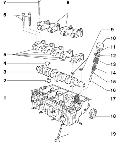
45.2 Timing mechanism parts
1 Cylinder head
2, 4 Camshaft bearing shells
3 Camshaft
5 Camshaft Bearing Caps
6 Bolt, to be replaced, 8 Nm, then tighten to an angle of 90°
7 Bolt, to be replaced, 20 Nm, then tighten to an angle of 90°
8 Rocker arm axle
9 Cylinder head bolt washers, insert into head before installing covers 5
10 Hydraulic valve clearance compensator
11 Split valve lock crackers
12 Plate of springs 13 and 14
13 Outer spring
14 Inner spring
15 Oil deflector cap
16 Valve sleeve
17 Injector pump
18 Seal
19 Valves
Material is available on the website: www.SKODABOOK.ru