
Cylinder head parts for 1.0L 37kW and 1.4L 50kW engines
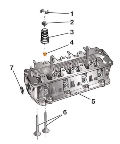
1 - valve cracker; 2 - valve spring plate; 3 - valve spring; 4 - oil scraper cap; 5 - block head; 6 - valve; 7 - plug
Valve seat
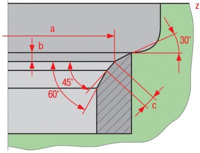
a is the seat diameter; b is the maximum allowable processing size; c is the width of the working chamfer; z - bottom plane of the block head
Measurement of valve protrusion above the spring seat in the engine head
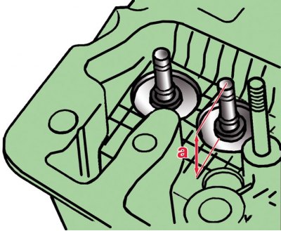
a - the size from the end of the valve to the bearing surface of the valve spring on the block head
Measuring the distance between the end face of the valve and the upper plane of the head of the diesel engine block 1.9 l, 74 kW
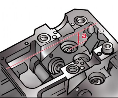
a - the distance from the valve end to the upper plane of the block head
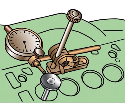
Measuring the gap between the valve and the guide sleeve
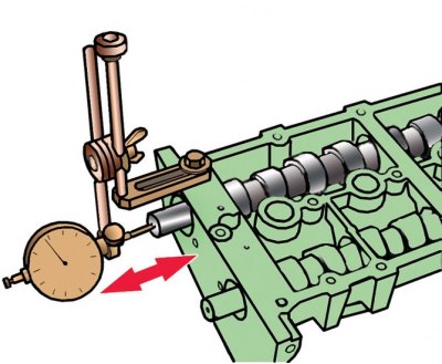
Measuring the axial clearance of the camshaft
Checking the flatness of the cylinder head
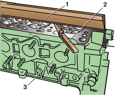
1 - ruler; 2 - probe; 3 - block head
Measuring the cylinder head height of a 1.4L engine
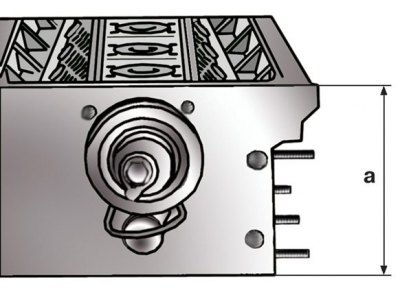
a - the height of the cylinder head
Valve dimensions
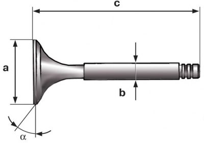
a is the diameter of the plate; b is the rod diameter; c - valve length
1. After disassembly, clean all parts from dirt, soot, oil, etc.
2. Check the flatness of the surface of the block head adjacent to the cylinder block. To do this, place a metal ruler with an edge on the surface of the head, first in the middle along the axis of the head, and then diagonally and measure the gap between the plane of the head and the ruler with a feeler gauge, as shown in the figure (see fig. Checking the flatness of the cylinder head). The maximum allowable clearance for gasoline engines is 0.05 mm, for diesel engines - 0.1 mm.
3. If the measured gap exceeds the maximum allowable, the block head must be replaced. For gasoline engines of 1.4 l, 55 and 74 kW, surface grinding is allowed, but the height a of the head must not be less than 108.25 mm (see fig. Measuring the cylinder head height of a 1.4L engine). If, as a result of grinding, the height of the head is reduced, it must be replaced.
Attention! After grinding the block head, it is necessary to grind the valve seats by the same amount as the head was ground so that the valves sit deeper, otherwise they will hit the pistons.
4. For engines 1.0 l, 37 kW and 1.4 l, 50 kW, check that plug 7 is firmly in place (see fig. Cylinder head parts for 1.0L 37kW and 1.4L 50kW engines), if not, replace it. To do this, knock out the old plug. Apply Loctite 270 around the perimeter of the new plug and press it flush into the head of the block.
5. Inspect the head: if there are cracks or burn marks in the combustion chambers, the head must be replaced. For diesel engines, small cracks between valve seats are allowed if their width does not exceed 0.5 mm. Replace valves with deep scratches and scratches on the working chamfer, with cracks, stem deformation, disc warping, traces of burnout. Shallow risks and scratches on the working chamfer can be removed by lapping the valves.
6. In a specialized workshop, the working chamfers of valves with damage that cannot be removed by lapping can be ground on a special machine. When grinding, it is necessary to withstand the dimensions indicated in Table. Valve dimensions and shown in the figure (see fig. Valve dimensions).
7. Check the condition of the valve springs: bent, broken or cracked, replace.
8. Inspect the valve lifters, if there are scuffs, chips, deep scratches, signs of stepped or uneven wear on their working surfaces, replace the pushers.
9. Inspect the camshafts, if their necks and cams have signs of wear, scuffs, chips, deep risks, etc., the shafts must be replaced.
10. Check the condition of the valve seats. The seat bevels must be free of wear, pitting, corrosion, etc. Minor damage (small risks, scratches, etc.) can be removed by lapping the valves.
11. In a specialized workshop, the working chamfers of seats with damage that cannot be removed by lapping the valves can be ground or milled. On fig. Valve seat and in the table. The valve seat dimensions indicate the dimensions of the 1.0 l, 37 kW and 1.4 l, 50 kW motors, which must be maintained during processing. First you need to calculate the maximum allowable size of the processing of saddles. For the specified motors, this dimension is determined as follows:
- insert the valve into the head and press against the seat. You need to insert the valve that will be installed in this seat;
- measure size a (see fig. Measurement of valve protrusion above the spring seat in the engine head) from the end face of the valve to the bearing surface of the valve spring on the block head;
- Calculate the maximum allowable machining size of seats using the formula:
b = a max - a,
where b is the maximum allowable size of the processing of saddles, mm; a max - maximum permissible valve protrusion (see table. Maximum allowable protrusion of valves) above the bearing surface of the spring on the head of the block, mm; a is the measured dimension from the end face of the valve to the bearing surface of the spring on the head, mm.
For example, for the intake valve of an engine with a displacement of 1.0 liters, the measured distance a is 42.7 mm, then b = 43.1 - 42.7 = 0.4 mm, i.e. the maximum depth of the seat is 0.4 mm.
12. If, as a result of the calculation, b equals 0, the measurement must be repeated with a new valve; if in this case it turns out zero, you need to replace the head.
13. For diesel engines 1.4 l, 74 kW distance a (see fig. Measuring the distance between the end face of the valve and the upper plane of the head of the diesel engine block 1.9 l, 74 kW) from the end face of the valve to the upper plane of the block head is determined as follows:
- insert the valve into the block head and press against the seat. You need to insert the valve that will be installed in this seat;
- measure size a;
- Calculate the maximum machining size of seats using the formula:
b = a - a min,
where b - the maximum size of the processing of saddles, mm; a is the measured size, mm; a min is the maximum allowable size from the end of the valve to the upper plane of the block head.
14. The maximum allowable size is 43.4 mm for the intake valve, and 43.2 mm for the exhaust valve.
15. For example, for an inlet valve, the measured distance a is 44.1 mm, then b = 44.1 - 43.4 = 0.7 mm, i.e. the maximum depth of the seat is 0.7 mm.
16. If the calculation results in b being zero, repeat the measurement with a new valve; if in this case it turns out zero, you need to replace the block head.
17. Check clearances between guide bushings and valves as follows:
- insert the valve into the guide sleeve so that the end of its stem is flush with the end of the sleeve. You need to insert the valve that will be installed in this sleeve;
- fasten the indicator so that its leg rests against the valve disc, as shown in fig. Measuring the gap between the valve and the guide sleeve. Press the valve towards the indicator until it stops and set the indicator to zero in this position. Then move the valve in the opposite direction until it stops and determine the amount of valve movement from the indicator. The maximum allowable valve travel for gasoline engines is 0.5 mm for the intake valve and 0.6 mm for the exhaust valve; for diesel engines - 1.3 mm for intake and exhaust valves. If the measured value exceeds the specified dimensions, the measurement must be repeated with a new valve; if it exceeds again, replace the block head.
18. Check the camshaft end play. To do this, for gasoline engines 1.4 l, 55 and 74 kW:
- place camshafts 27 (see fig. Details of the cylinder head of engines 1.4 l, 55 and 74 kW) in the bearing housing 5 and install the rear covers 7 and 11, tightening the bolts 8 of their fastening to a torque of 10 Nm;
- fix the indicator so that its leg rests against the end of the camshaft, as shown in fig. Measuring the axial clearance of the camshaft. Move the camshaft towards the indicator until it stops and in this position set the indicator to zero. Then move the camshaft in the opposite direction until it stops - the indicator will show the value of the axial clearance.
19. In the same way, measure the axial clearance of the other camshaft. Axial clearance for diesel engines is measured in the same way, but their camshaft is installed in the head of the block (with valve lifters removed) and is secured by the covers of the first, third and fifth bearings. The axial clearance for all motors must not exceed 0.15 mm.
Valve sizes
Engine | Inlet/outlet valve | ||
Diameter plates a, mm | Diameter rod b, mm | Length valve s, mm | |
| Petrol 1.0 l, 37 kW | 34,0/ 27,0 | 7,0/ 7,0 | 104,0/ 104,0 |
| Petrol 1.4 l, 50 kW | 34,0/ 30,0 | 7,0/ 7,0 | 101,0/ 101,0 |
| Petrol 1.4 l, 55 and 74 kW | 29,5/ 26,0 | 5,973/ 5,953 | 100,9/ 100,5 |
| Diesel 1.9 l, 74 kW | 35,95/ 31,45 | 6,980/ 6,956 | 89,95/ 89,95 |
Valve seat dimensions
Engine | Size | Inlet valve | Exhaust valve |
| Petrol 1.0 l, 37 kW | Valve seat diameter, mm | 33,4 ± 0,1 | 26,4 ± 0,1 |
Working chamfer width, mm | 1,3 – 1,6 | 1,3 – 1,6 | |
| Petrol 1.4 l, 50 kW | Valve seat diameter, mm | 32,9 ± 0,1 | 29,6 ± 0,1 |
Working chamfer width, mm | 1,45 – 1,75 | 1,65 – 1,95 |
Maximum allowable protrusion of valves
Engine | Inlet valve | Exhaust valve |
1.0 l, 37 kW | 43.1 mm | 43.0 mm |
1.4 l, 50 kW | 42.7 mm | 42.8 mm |