
Cylinder head assembly with valve type timing mechanism
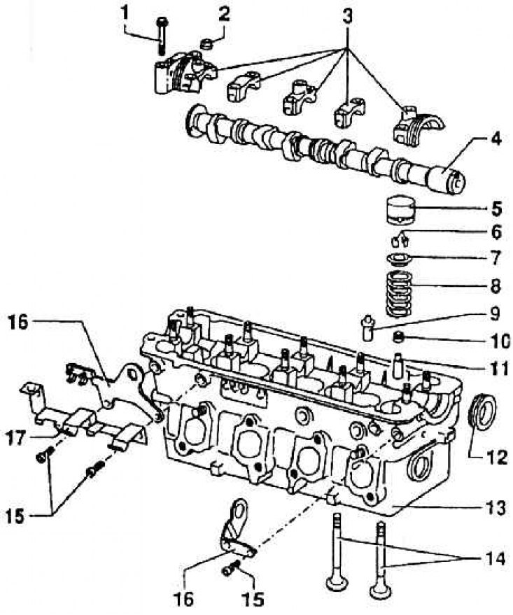
1 – a bolt of fastening of covers of the bearing of a cam shaft; 2 – a nut of fastening of covers by the bearing of a cam shaft; 3 - camshaft bearing caps; 4 - cam shaft; 5 – a glass of a hydraulic pusher; 6 - valve crackers; 7 - valve spring plate; 8 - valve spring; 9 - valve guide (for repair); 10 - valve stem seal; 11 - valve guide; 12 - sealing ring of the cam shaft; 13 – a head of the block of cylinders; 14 - valves; 15 – a bolt of fastening of an earring; 16 - earring; 17 – an arm of a wire of ignition
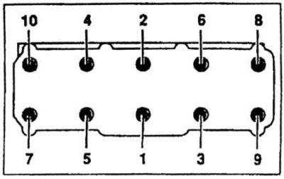
The order of tightening the bolts on the cylinder head
Hydraulic pusher diagram
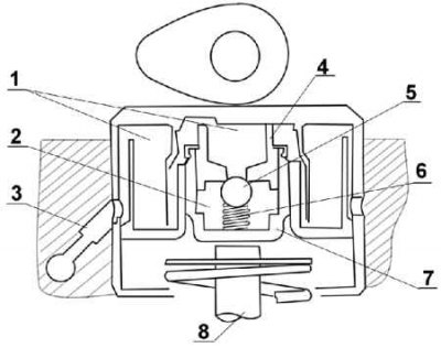
1 - spare volume of oil; 2 – high pressure chamber; 3 - oil supply; 4 - piston; 5 - shut-off valve; 6 - valve spring; 7 - inner sleeve; 8 - engine valve
Since the engine is equipped with an ONS gas distribution mechanism, it is considered that the cylinder head assembly includes a camshaft with installation elements, and valves with accessories, and a head cover with a seal, and a seal for the cylinder head and other related parts (see fig. Cylinder head assembly with valve type timing mechanism). The entire cylinder head is attached to the crankcase with ten special threaded bolts M 11x1.5. The bolt heads have a star-shaped polyhedron inside for a special key. The unevenness of the bearing surface of the block head should not exceed 0.05 mm.
A dry seal is placed between the block and the head. There are metal rings on the seal around the cylinders, and a silicone lip along the outer contour. The seal reinforcement is made of aluminized steel sheet. The head on the block is centered with two steel pins. The bolt tightening stroke is carried out at all stages in the order shown in fig. The order of tightening the bolts on the cylinder head; weakening is carried out in the reverse order and also in stages.
The bolts are tightened in four stages. First tighten to 40 Nm, then to 60 Nm. At the third stage, all the bolts are rotated by 90, and at the fourth, last stage, by another 90±10%. Then, during operation, the bolts must not be tightened.
The cylinder head is cast from aluminum alloy. It is eight-channel, which means that it has four exhaust channels and four suction channels. Exhaust ducts are brought to the left side of the engine (forward in the direction of travel), suction channels on the reverse side. On the same, right side, there are also holes for spark plugs.
Valve seats and valve guides are pressed into the block head casting. Both are made from a special alloy. Guides can be changed, saddles cannot.
Part of the head, in which the lower halves of the five bushless camshaft bearings are located, are also the covers of these bearings. On the upper surface of the outer covers and the middle cover there are bosses with threaded holes for fixing bolts of the head cover. O-rings are inserted into the outer bearings, adjacent to the cylindrical surface of the camshaft. When installing the suction pipe and exhaust manifold, M8 bolts are screwed into the head casting.
Inlet valves have a plate diameter of 35.6±0.15 mm, exhaust valves - 29±0.15 mm.
Each valve stem is sealed with an O-ring seated on the valve guide. Each valve has one steel wire coil spring. A valve spring plate is superimposed on it, to which the valve is attached with two wedges.
The transmission of movement and forces between the camshaft cams and valves is carried out by hydraulic pushers, which automatically limit the valve clearance during operation. This, of course, is an advantage, but, of course, due to increased requirements for the engine lubrication system (need high purity oil). There is also a slightly increased passive resistance of the engine due to the fact that the pushrods are in constant contact with the cam, namely in its cylindrical part.
The principle of operation of the hydraulic pusher (see fig. Hydraulic pusher diagram). The upward movement of the pushrod, caused by the difference in oil pressure between the volumes between which the ball valve is placed, opens this valve. When it moves back, caused by the piston being intentionally slightly loose, the spring is compressed and oil flows through the ball valve into the high pressure chamber from the engine lubrication system. In this way, the valve clearance is automatically limited.
The labyrinth in the spare chamber prevents the outflow of oil when the engine is turned off.
Hydraulic pushers cannot be repaired.