



Contents: Removal ⬇ Installation ⬇
Removal
1. Turn off the ignition. Disconnect the negative terminal from the battery.
2. Remove the lower protective cover of the engine compartment.
3. Drain the coolant into a previously prepared container.
4. Remove the upper timing chain cover (more details, see the relevant section in this chapter).
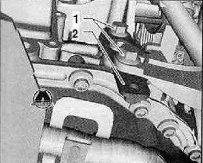
5. Loosen the mounting screws (1) and remove the coolant pipe holder (2) as shown in the figure below.
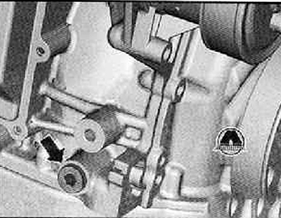
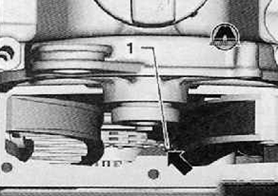
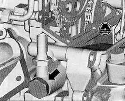
6. Unscrew the threaded plug (arrow) from the cylinder block, as shown in the figure below.
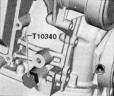
7. Screw the "T10340" locking screw into the cylinder block until it stops, as shown in the figure below.
Attention. If you cannot screw in the locking screw "T10340" all the way, this means that the crankshaft is not in the correct position. In this case, you must do the following:
- Unscrew the locking screw.
- Turn the crankshaft 90° (¼ turn) in the direction of engine shaft rotation.
- Screw the fixing screw "T10340" into the cylinder block until it stops.
- The fixing screw "110340" should be tightened to a torque of 30 Nm.
8. Turn the crankshaft until it stops in the direction of rotation of the engine shaft.
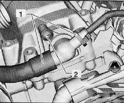
9. Disconnect both coolant hoses (1) from the check valve as shown in the figure below.
10. Unscrew the fastening screw (2), remove the check valve from the cylinder head cover.
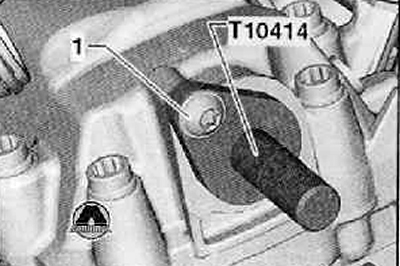
11. Install the "T10414" locking bolt until it stops against the cylinder head cover, as shown in the figure below.
12. Tighten the mounting screw (1) shown in the figure below by hand.
13. Remove the oil pan.
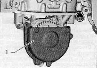
14. Remove the oil pump drive chain cover (1) as shown in the figure below.
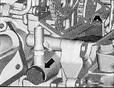
15. Unscrew the tensioner (arrow) of the camshaft drive chain, as shown in the figure below.
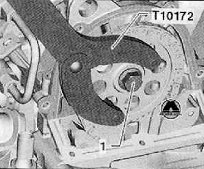
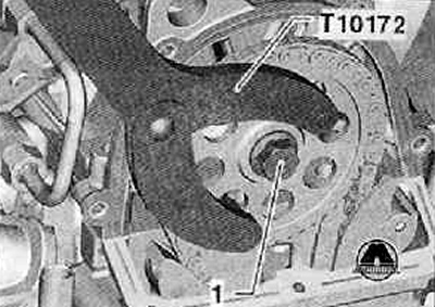
16. Holding the camshaft drive gear using the T10172 locking counter support, loosen the camshaft drive gear mounting bolt (1), as shown in the figure below.
17. Remove the camshaft drive gear together with the mounting bolt.
18. Place the camshaft drive chain (1) on the lug (arrow) of the timing chain cover, as shown in the figure below.
Note: The boss on the inside of the timing chain cover prevents the camshaft timing chain from falling off.
19. Disconnect the hose leading to the air filter from the cylinder head cover.
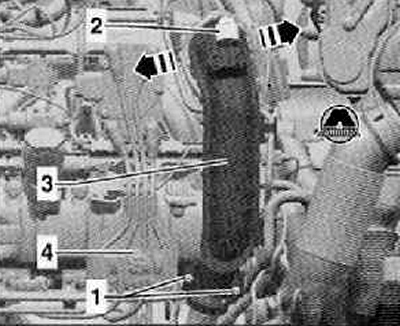
20. Unscrew the mounting screws (1) and remove the mounting clamp, as shown in the figure below.
21. Disconnect the wiring harness connector (2) at the boost pressure sensor "G31" shown in the figure below.
22. Unlock the fasteners in the direction of the arrow, disconnect the pressure pipe (3) first from the throttle valve module "J338" and then from the turbocharger, as shown in the figure below.
23. Remove the cover and unscrew the fastening screw (4), shown in the figure below.
24. Using a special puller "T10112A", disconnect the high-voltage wires from the spark plugs. Put the high-voltage wires aside.
25. Remove the high pressure pump.
26. Disconnect the wiring harness connectors from the fuel injectors.
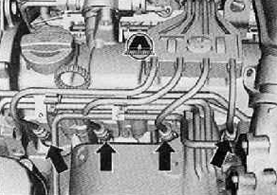
27. Unscrew the mounting screws (arrows) shown in the figure below and remove the fuel rail.
28. Remove the turbocharger assembly (for more details, see the relevant section in the chapter Intake and exhaust system).
29. Disconnect the wiring harness connector from the Hall sensor "G40".
30. Remove the oil level indicator.
31. Loosen the cylinder head cover mounting bolts crosswise from the outside towards the inside and unscrew them.
32. Carefully remove the cylinder head cover.
Note: Prevent dirt and sealant residue from entering the cylinder head.
Installation
Attention.
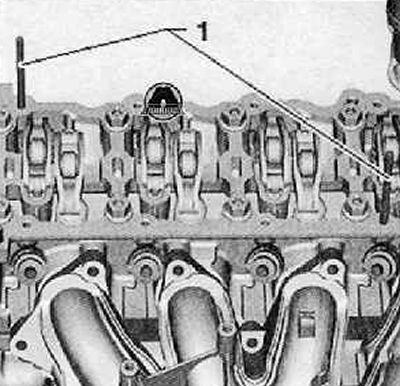
- Before installing the cylinder head, the studs (M6x70) must be screwed into the cylinder head.
- The cylinder head cover is guided by studs, thus preventing the rocker arms from slipping off the hydraulic tappets.
Note: Neither piston should be at TDC.
Caution: When working with the seal remover and degreaser, wear protective gloves and goggles.
1. Remove any remaining sealing agent (sealant) from the sealing surfaces on the cylinder head cover and cylinder head with a chemical seal remover.
2. Degrease the sealing surfaces.
3. Before installing the cylinder head cover, it is necessary to screw two studs (M6 x 70) (1) into the cylinder head.
Please note: The cylinder head cover is sealed using 2 different sealing agents.
Note: Do not apply the sealant too thickly, otherwise excess sealant may enter the oil holes and cause engine damage.
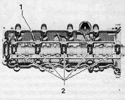
4. Apply the sealing agent (sealant) "D 189 500 A1" to the welded surface (1), as shown in the figure below. The diameter of the sealing agent roller should be 2...3 mm and it should be applied on the inside of the screw holes.
5. Apply a thin layer of sealing agent "D 154 103 A1" evenly to the surfaces marked with hatching in the figure below (2).
6. Check that the rocker arms are in contact with the hydraulic compensators.
7. Carefully place the cylinder head cover over the studs and dowel pins onto the cylinder head.
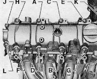
8. Tighten the new cylinder head cover mounting screws in the following sequence from "A" to "J". Tightening torque 8 Nm + an additional 90° (¼ turn).
Attention.
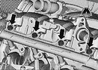
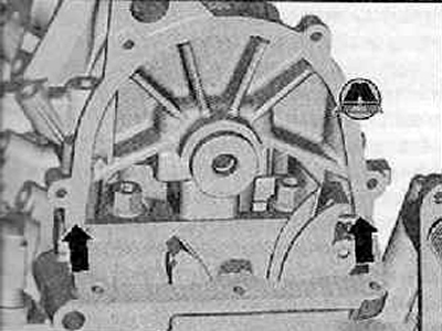
- It is imperative to remove the sealing agent for the cylinder head cover in the area shown in the figure below (arrows).
- To avoid leaks, do not mix both sealants for the cylinder head cover and the timing chain housing.
9. Remove excess sealant from the area shown in the figure below (arrows).
10. Turn the crankshaft until it stops in the direction of rotation of the engine shaft.
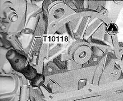
11. Raise the camshaft drive chain using the T10118 installation tool as shown in the figure below.
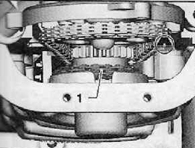
12. Check from below that the camshaft drive chain (1) is correctly positioned on the crankshaft gear, as shown in the figure below.
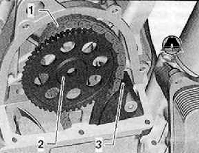
13. Place the camshaft drive chain (1) onto the chain drive sprocket (2) as shown in the figure below.
14. At the guide rack section (3), the camshaft drive chain should be snug and slightly taut, as shown in the figure below.
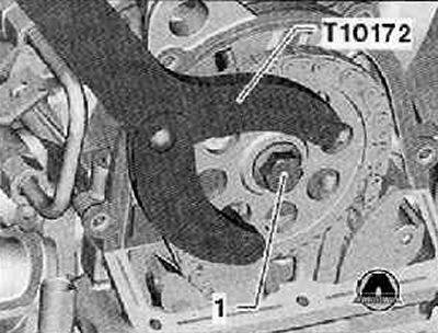
15. Hold the camshaft drive gear with the T10172 locking counter support and tighten the camshaft drive gear mounting bolt (1) to a tightening torque of 50 Nm, as shown in the figure below. The mounting bolt should only be turned 90° (¼ turn) after checking the valve timing at the end of the working process.
16. Tighten the chain tensioner to a torque of 60 Nm.
17. Remove the lock bolt "T10414" from the camshaft.
18. Unscrew the locking screw "T10340" from the cylinder block.
19. Turn the crankshaft two revolutions in the direction of rotation of the engine shaft.
20. Screw the fixing screw "T10340" into the cylinder block until it stops.
21. Turn the crankshaft until it stops in the direction of rotation of the engine shaft.
Article reprinted from the website: skodabook.ru
22. The valve timing is adjusted if it is possible to install the "T10414" fixing bolt into the camshaft.
If the distribution in time is not normal
23. Repeat the adjustment of the valve timing (more details, see the relevant section in this chapter).
24. Holding the camshaft drive gear using the T10172 locking counter support, turn the mounting bolt (1) 90° (¼ turn), as shown in the figure below.
25. Remove the fixing bolt "T10414" and the fixing screw "T10340".
26. Install the upper timing chain cover (more details, see the relevant section in this chapter).
27. Install the turbocharger assembly with the exhaust manifold (for more details, see the corresponding section in the chapter Intake and exhaust system).
28. Install the oil pan.
29. Install the crankshaft pulley.
30. Install the high pressure pump.
31. Install fuel lines.
32. Further installation is carried out in the reverse order of removal.