
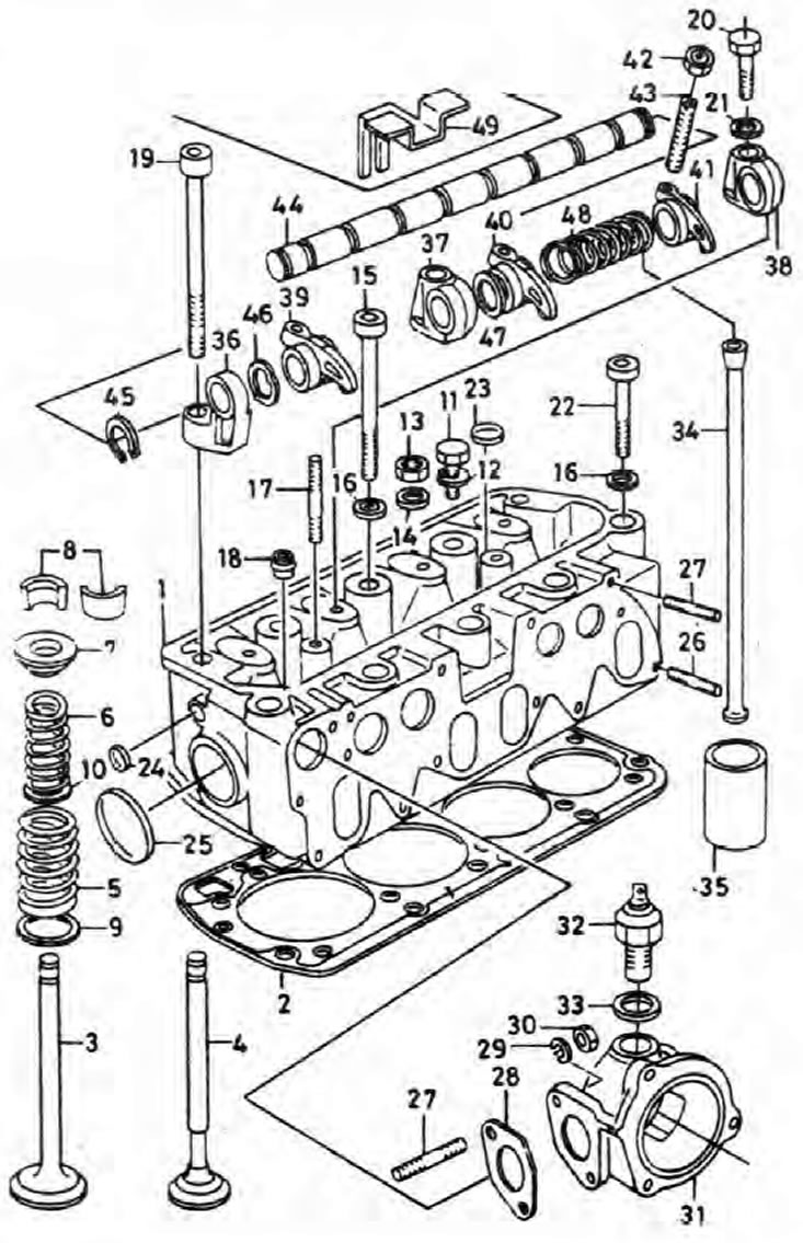
Pic. 2A.3. Cylinder head and components mounted on it
1. Cylinder head; 2. Laying under a head of the block of cylinders; 3. Inlet valve; 4. Exhaust valve; 5. External valve spring; 6. Internal valve spring; 7. Spring support cup; 8. Valve crackers; 9. External spring support; 10. Internal spring support; 11. Bolt-bracket of the generator to the cylinder head; 12. Spring washer; 13. Nut of fastening of a head of the block of cylinders; 14. Flat washer; 15. Bolt of fastening of a head of the block of cylinders; 16. Flat washer; 17. Valve cover pin; 18. Valve guide oil scraper cap; 19. Bolt of fastening of a head of the block of cylinders; 20. Bolt-valve mechanism to the cylinder head; 21. Flat washer; 22. Bolt of fastening of a head of the block of cylinders; 23. Cork; 24. Cork; 25. Cork; 26. Hairpin; 27. Hairpin; 28. Gasket; 29. Spring washer; 30. Nut - thermostat casing to the cylinder head; 31. Thermostat cover; 32. Coolant temperature indicator sensor; 33. Sealing washer; 34. Push rod; 35. Pusher; 36. Support of the riveted mechanism; 37. Valve mechanism support; 38. Valve mechanism support; 39 rocker; 40. Rocker; 41. Rocker; 42. Rocker adjusting screw locknut; 43. Rocker adjusting screw; 44. Axis of rocker arms; 45. Retaining ring; 46. Curved washer; 47. Flat washer; 48. Spring; 49. Oil shield.
Removing
1. Disconnect the negative cable from the battery.
2. Drain the cooling system as described in Section 1.
3. Remove the air filter assembly as described in Section 4.
4. Remove the valve train as described in Chapter 5.
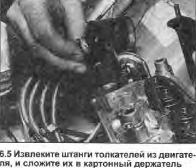
5. Remove the push rods one by one (see illustration) and stack them in the correct order in a cardboard holder with numbered holes. When assembling, the rods must be installed in their original places.
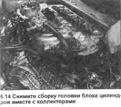
6. Please note that in the following description, the cylinder head is removed together with the manifolds.
7. Proceed as described in Section 4, disconnect the exhaust outlet pipe from the manifold.
8. Disconnect the following from the fuel system and intake manifold:
- a) Wiring connector.
- b) Gas pedal cable.
- c) Brake booster unit hose.
- d) Hoses of the cooling system.
9. Disconnect the wiring connector from the coolant temperature gauge sensor. Disconnect the upper radiator hose and expansion tank hose from the thermostat housing (see illustration).

10. Loosen and remove the alternator's top mounting bolt, and free the alternator from the top bracket.
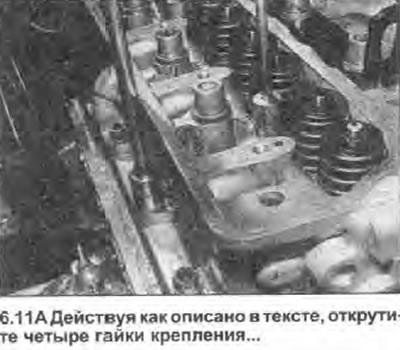
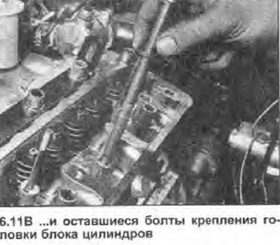
11. Working in the reverse order shown in illustration 6.26A, gradually loosen the four fastening nuts on the front edge of the cylinder head, and remove them. In the same sequence, loosen the eight remaining cylinder head bolts one turn at a time. Remove bolts with washers (see illustrations), and store them in the correct order. Note the location of the engine mounting lug attached by rattling the rear bolts.
 |  |
12. Now you need to break the connection between the cylinder head, gasket and cylinder block / crankcase without disturbing the cylinder liners; there is a possibility of coolant and foreign particles entering the sump if the cylinder head is lifted carelessly. If precautions are not taken and the sleeves are disturbed, there is also the possibility of the lower seal being broken, which will also lead to leaks.
Warning: If the cylinder liner base seal is broken, the pistons and liners must be removed to install a new seal.
13. To break the connection, use the exhaust manifold as a support for the lever, and carefully tear off the cylinder head from the front of the car.
14. When the connection is broken, lift the cylinder head (see illustration). Remove the gasket - it must be replaced.
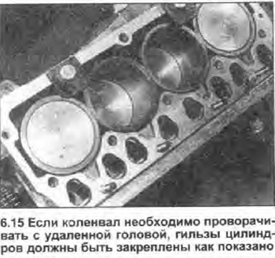
15. Do not attempt to crank the crankshaft with the cylinder head removed. cylinder liners may be displaced. Operations that typically involve crankshaft rotation (e.g. cleaning piston heads), must be carried out with great care so that no dirt particles get inside. If it is necessary to rotate the crankshaft, the cylinder liners must be secured with a pair of suitable bolts and large flat washers (see illustration).
16. If the cylinder head needs to be disassembled, refer to the relevant chapters later in this Section.
Preparing for installation
17. Check up a condition of bolts of fastening of a head of the block of cylinders, paying special attention to a carving. Rinse and dry all bolts, then inspect each for wear or damage, and replace suspicious ones if necessary. It is recommended to replace the bolts as a complete set each time they are removed, regardless of condition.
18. Before installing the head, clean the mating surfaces of the cylinder head, cylinder liners and crankcase. Using a plastic or wooden scraper, remove the remnants of the gasket and soot; also clean the piston heads. Be very careful not to scratch the aluminum surfaces. Also keep an eye on it. so that carbon deposits do not enter the lubrication and cooling channels - this is especially important for the lubrication system, as the oil supply to engine components can be blocked. Use tape and paper to seal all passages and bolt holes in the cylinder block/crankcase. To prevent carbon deposits from getting between the pistons and cylinders, fill the space between them with a small amount of grease. After cleaning the piston, remove grease and deposits from the gap using a small brush, then wipe off the residue with a clean rag. Clean all pistons in the same way.
19. Check the contact surfaces of the cylinder block/crankcase and cylinder head for nicks. deep scratches and other damage. Minor scratches can be removed with a file, and for excessive damage, regrinding may be the only alternative to replacement.
20. If it is suspected that the landing surface of the cylinder head is deformed, then setting the steel ruler on the edge, check this.
Installation
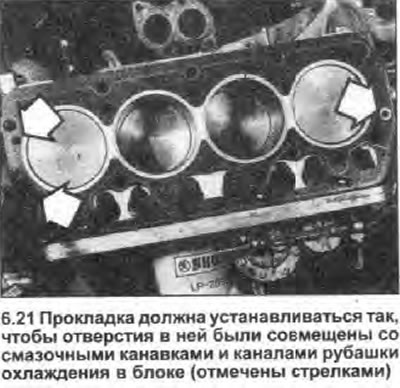
21. Wipe the contact surfaces of the head and cylinder block/crankcase, then place a new gasket on the surface of the cylinder block. Install the gasket so that the holes in it are aligned with the oil grooves on the left and right ends of the cylinder block (see illustration).
22. Put the cylinder head on the studs, and carefully lower it into place.
23. Keeping the installation order, wash and wipe dry all cylinder head bolts and washers (if you haven't already), then lightly lubricate the heads and threads of the bolts. Carefully insert the bolts (except for two, which are also used to mount the valve train bearings) into the old holes. Don't forget to install the motor mounting lug. Screw in each bolt by hand as far as possible.
24. Remove the pusher rods from the cardboard holder, and insert them into their original places in the cylinder head.
25. Install the valve train as described in Chapter 5. Tighten the four small internal mounting bolts to the specified torque, and then hand-tighten the two cylinder head bolts.
26. Working in the illustration shown (numbers 1-10) sequences, in several specified in Specifications stages, tighten the cylinder head bolts. To tighten the bolts to those specified in Specifications corners, use a felt-tip pen to draw a line between the cylinder head and the outer edge of each bolt head; in the second stage, each bolt is turned 90° (quarter turn). In the third stage, the bolts are turned 90°again. If any bolt is overtightened past the mark, loosen it 90°and then retighten (see illustrations).
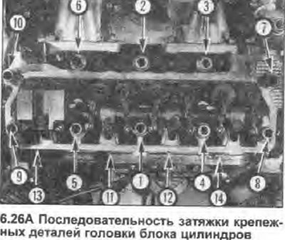 | 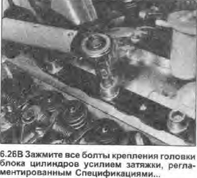 |
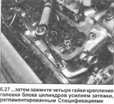
27. After all ten bolts are properly tightened, apply a little engine oil to the cylinder head nuts. Install the nuts and washers on the studs located on the front edge of the cylinder head. In the one shown in illustration 6.26A (numbers 11-14) order, tighten the four nuts with a tightening torque regulated specifications (see illustration).
28. Adjust the valve clearances, then install the valve cover as described in Chapter 4 of this Section.
29. Attach all disturbed cooling system hoses, and connect the electrical wiring of the coolant temperature sensor. Recommended old Skoda hose clamps (where there are) replace with standard worm clamps.
30. Acting as described in the relevant Section 4 chapters, connect all wiring and hoses to the intake manifold and fuel system components. Connect and adjust the throttle cable.
31. Acting as described in Section 4, connect the exhaust outlet pipe to the manifold.
32. Install the alternator top mounting bolt and adjust the drive belt tension as described in Section 1.
33. Install the air filter assembly as described in Section 4 and connect the negative cable to the battery.
34. Fill the cooling system as described in Section 1.