
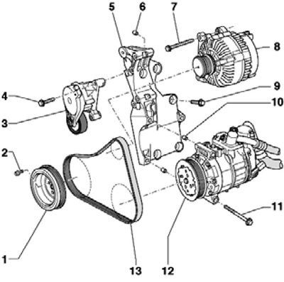
43.1 Installation details of the accessory drive belt
1 crankshaft pulley
2 Bolt, to be replaced, 10 Nm, then retighten 90°
3 Belt tensioner 13
4, 7 Bolt, 23 Nm
5 Auxiliary bracket
6, 10 Centering sleeves
8 Generator
9 Bolt, 45 Nm, tightened with fixing sealant D000 600A2
11 Bolt, 25 Nm
12 Air conditioner compressor
13 Auxiliary drive belt
2. Timing belt installation details are indicated on the resist. illustrations.
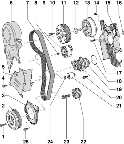
43.2 Timing belt installation details
1 Bolt, to be replaced, 10 Nm, then retighten to 90
2 crankshaft pulley
3 Rear lower timing belt cover
4, 14, 25 Bolt, 10 Nm, tightened with fixing sealant D000 600A2
5 The central casing of the timing belt, to remove, remove the casing 6 and the auxiliary drive belt tensioner
6 Upper timing belt cover, to remove, remove the right pressure air tube
7 Timing belt
8 Nut, 20 Nm, then tighten 45°
9 Tension roller
10 Bolt, 20 Nm, then retighten 45°
11 Camshaft gear
12 Bolt, 100 Nm
13 Wheel hub 11, with CMP sensor rotor
14 Bolt, 10 Nm
15 Rear timing belt cover, to remove, remove the water pump
16 Rubber stopper
17 Bolt, 25 Nm
18 O-ring
19 Water pump
20 Bolt, 13 nm
21 Intermediate roller
22 Crankshaft gear, there must be no grease between the shaft and the wheel
23 Bolt, to be replaced, 120 Nm, then tighten 90°, do not lubricate
24 Nut, 22 Nm
Removing the timing belt
3. Remove the accessory drive belt.
4. Remove the pressure air hose.
5. Give the fasteners of the expansion tank and set it aside, without disconnecting the coolant hoses, on the cylinder head.
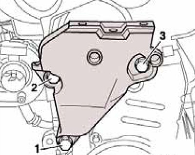
6. Press the tabs and remove the feed (2 to resist. illustrations) and return (1) fuel lines.
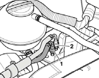
43.6 Fuel lines
7. Press the latches (see resist. illustration) and remove the upper timing belt cover.
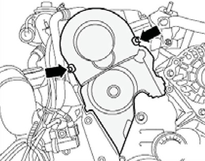
43.7 Fasteners for upper timing belt cover
8. Remove the accessory drive belt tensioner.
9. Remove the right front wheel arch locker.
10. Remove the crankshaft pulley. Remove the lower and middle timing belt covers.
11. Install the beam MP9-200 (№10-222A) and unload the engine mount using the MP9-200/10 hook (№10-222А/1 0), hooked to the right lifting eye.
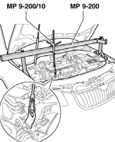
43.11 Unloading power unit supports
12. Turn out bolts (1-2 per resist. illustrations) and remove the connecting pin. Loosen the bolts (3-6) and remove the engine console.
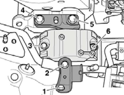
43.12 Removing the engine console
13. Turn out bolts (1-3 per resist. illustrations) and remove the engine mount. If necessary, lower/raise the engine slightly when removing the bolts.
43.13 Engine mount
14. Turn the crankshaft clockwise by its front central bolt to the TDC position. At the same time, a slot with teeth (1 per resist. illustrations) should be on top, and the foot (1) rotor of the CMP sensor should be opposite the mark (2) on the rear timing belt cover.
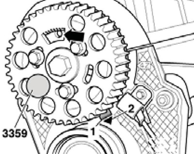
43.14 TDC marks on the camshaft gear
Note: For clarity, the timing belt is not shown in the illustration.
15. Lock the hub with pin N°3359 and also lock the crankshaft sprocket by sliding tool T10100 over it from the front. The stud of tool T10100 must fit into the hole in the front sealing flange, and the arrow on tool T10100 must be opposite the mark on the crankshaft gear (see resist. illustration).
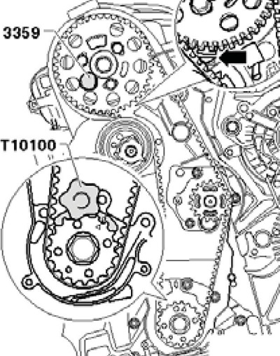
43.15 Fixation at TDC
16. If the timing belt is to be reused, mark the direction of its movement on it. Loosen the camshaft gear mounting bolts one turn (see resist. illustration).
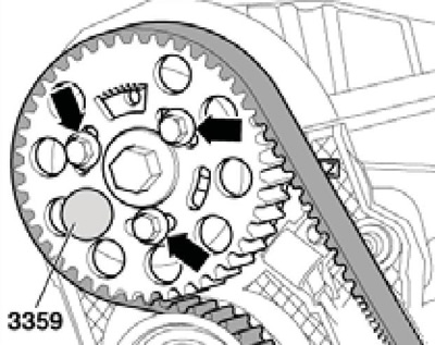
43.16 Camshaft gear bolts
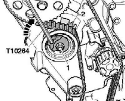
17. Loosen the nut (1 per resist. illustrations) timing belt tensioner, carefully turn the tensioner eccentric counterclockwise with a T10264 hexagon and lock it by inserting tool T10265.
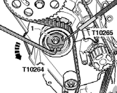
43.17 Timing belt loosening
18. Turn the timing belt tensioner clockwise until it stops and tighten the nut (1 per resist. illustrations) by hand. Remove the timing belt idler and remove the timing belt starting at the crankshaft.
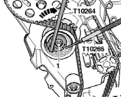
43.18 Fixing the timing belt tensioner
Timing belt installation, timing adjustment
Note: Timing timing adjustment should only be done on a cold engine. Do not rotate the camshaft when any of the pistons are at TDC - there is a risk of damage to the pistons and valves.
19. Make sure that the shafts are fixed with tools No. 3359 and T10100, and the timing belt tensioner is fixed with a nut in a loose position.
20. Make sure the idler pulley is correctly positioned in the hole in the rear timing belt cover (see resist. illustration).
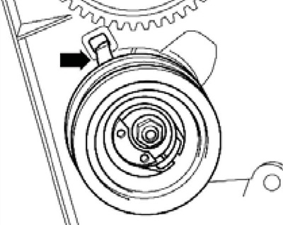
43.20 Position of the tensioner in the rear cover
21. Slightly screw in the camshaft gear bolts so that it does not hang out, but it is still possible to turn the gear on the hub. Turn the gear wheel clockwise in the oblong holes until it stops.
22. Put the timing belt on the crankshaft gear, idler pulley, camshaft gear and finally on the water pump gear.
23. Install the timing belt idler.
24. Remove tool T10265 from the tension roller. loosen the nut (1 per resist. illustrations) tension roller and turn its eccentric with a T1 0264 hexagon clockwise until the pointer (2) located in the center of the base plate gap. Make sure that the tensioner nut does not turn. While holding the tensioner eccentric in this position, tighten the tensioner nut with a force of 20 Nm, and then tighten it to an angle of 45°. When tightening the nut, the pointer rotates no more than 5 mm to the right from the gap in the base plate. This provision should not be corrected, as the timing belt will still fit.
43.24 Tensioning the timing belt
25. Fit counterholder T10172 and push it in the direction of the arrow (see resist. illustration). While holding the camshaft sprocket pulled, tighten the bolts (1) with a force of 20 Nm, and then tighten them to an angle of 45°. Remove retainers #3359 and T10100.
26. Rotate the crankshaft clockwise two turns until it is just before TDC. In this position, lock the camshaft hub again with lock #3359 (see illustration 43.14) and check that the crankshaft can be blocked with tool T10100 (see illustration 43.15), and the timing belt tensioner indicator is located no more than 5 mm to the right of the gap in the base plate. If these conditions are met, go to paragraph 28.
27. If the crankshaft cannot be blocked, loosen the camshaft gear mounting bolts and turn the crankshaft in the TDC area so that it can be installed with tool T10100. Block the crankshaft, retract the camshaft sprocket and tighten its bolts (20 Nm + 45°angle). Remove clamps N°3359 and T10100 again and check timing adjustment (go back to paragraph 26).
28. Install the remaining parts in the reverse order of their removal. Bolts of fastening of a support of the engine tighten in sequence (2-1-3 in Illustration 43.13) with a force of 40 Nm, and then tighten them through an angle of 180°.