



Contents: Petrol models 1.2 l ⬇ Petrol models 1.4 l ⬇ Petrol models 1.8 l: removal and…⬇ 1.8L Petrol Engines: Checking and…⬇ 1.8L Petrol Engines: Vacuum Block…⬇ Diesel engines 2.0 l (CFHC, CFJA and…⬇
Note: If a mechanical fault is detected in the turbocharger (for example, damage to compressor blades), in addition to replacing the turbocharger assembly itself, to prevent subsequent damage, you should make sure that the air supply tract is clean and free of foreign objects. If foreign objects are found in the boost system, the boost air lines should be cleaned and the intercooler should be replaced.
Petrol models 1.2 l
Note: The turbocharger can only be removed and replaced as a complete assembly with the exhaust manifold and boost pressure regulator.
1. Turbocharger installation details are shown in the illustrations.
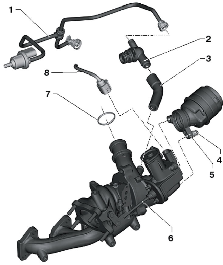
5.1a. 1.2L Petrol Turbocharger Connections, Part 1 of 2 1. Solenoid valve No. 1 "N80" purge of the adsorber, to the inlet pipeline; 2. Non-return valve, on the cylinder head cover; 3. Connecting hose; 4. Bolt, 8 Nm; 5. Connecting inlet pipe; 6. Turbocharger with exhaust manifold, with boost pressure regulator "V465"; 7. Sealing ring, subject to replacement; 8. Electrical wiring connector
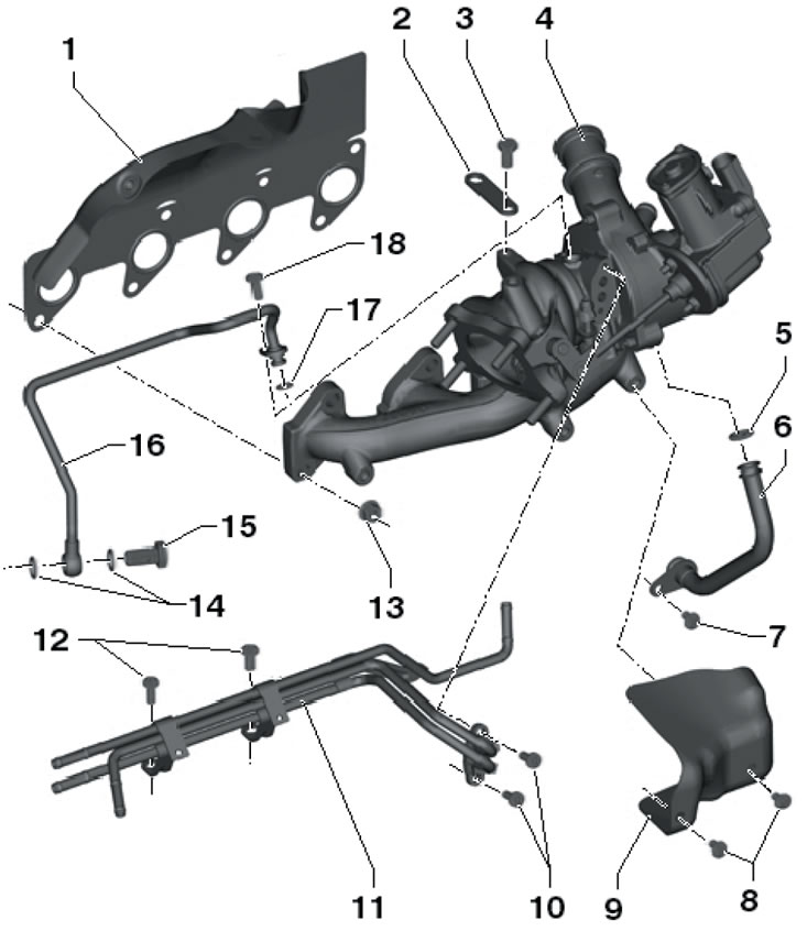
5.1b. 1.2L Petrol Turbocharger Connections, Part 2 of 2 1. Gasket, subject to replacement; 2. Bracket; 3. Bolt, 20 Nm; 4. Turbocharger with exhaust manifold, with boost pressure regulator "V465"; 5. Sealing ring, subject to replacement; 6. Return oil pipe; 7. Bolt, 8 Nm; 8. Bolts, 10 Nm; 9. Heat shield; 10. Bolts, 8 Nm; 11. Coolant pipe; 12. Bolts, 8 Nm; 13. Nut, subject to replacement, 18 Nm, then twice 12 Nm; 14. Sealing ring, subject to replacement; 15. Hollow bolt, 20 Nm; 16. Oil supply pipe; 17. Sealing ring, subject to replacement; 18. Bolt, 8 Nm
2. Disconnect the negative cable from the battery.
3. Remove the accessory drive belt (see Chapter 2).
4. Drain the coolant (see Chapter 3).
5. Disconnect the connector (2 in the illustration) and disconnect the hoses (1) from the turbocharger.
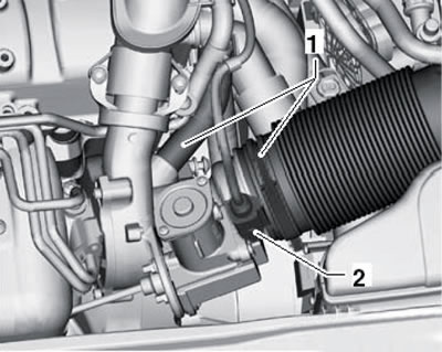
5.5. Turbocharger Hoses and Connector
6. Remove the bolts (1 in illustration 9.16 Chapter 2) and remove the holder. Disconnect the connector (2) of the boost pressure sensor "G31", combined with the IAT sensor No. 2 "G299". Press the clamps in the direction of the arrows and pull the pressure air tube (3) first from the throttle module "J338", and then from the turbocharger. Remove the plug (4) and unscrew the bolt located behind it. Disconnect the spark plug connectors using the T10112A puller (see Chapter 5) and put the high-voltage wires back.
7. Disconnect from the coolant pipes (1 in the illustration) coolant hoses and unscrew the hollow bolt (4) of the oil pipe. Remove the bolts (2 and 3) and separate the oil and water pipes. Remove the pre-catalytic lambda probe "G39" (5). Unscrew the upper generator mounting bolt and press it down slightly, then unscrew the bolts (arrows) and remove the heat shield from the turbocharger.
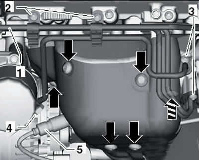
5.7. Removing the heat shield
8. Remove the bracket (1 in the illustration), release the nuts (arrows) on the turbocharger.
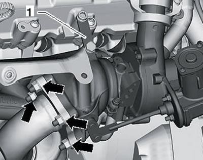
5.8. Connecting the turbocharger to the exhaust pipe
9. Remove the sound insulation under the engine compartment (see Chapter 11). Disconnect the connectors (1 in the illustration), loosen the nuts (2), unscrew the bracket bolts (3) and remove the catalytic converter downwards.
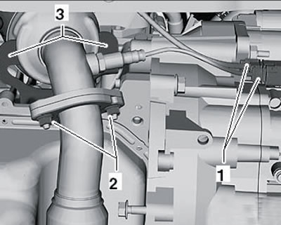
5.9. Removing the catalytic converter
10. Unscrew the bolt (1 in the illustration) return oil pipe (2) and pull it out of the turbocharger. Loosen the heat shield mounting bolts (3) and remove it from the exhaust manifold.
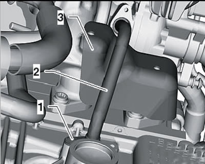
5.10. Removing the heat shield
11. Give all the nuts (A-N in the illustration) fasten the exhaust manifold to the cylinder head and remove the exhaust manifold together with the turbocharger. Remove the gasket from the studs and install a new gasket.
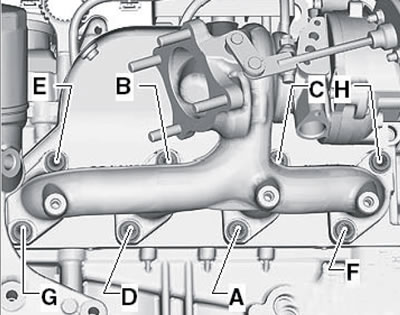
5.11. Fastening the turbocharger and exhaust manifold assembly
12. Install the exhaust manifold assembly with the turbocharger and tighten the new nuts securing it in the sequence (A-N in illustration 5.11) with a force of 18 Nm.
13. Further installation is carried out in reverse order. Use new gaskets, O-rings and self-locking nuts. Before connecting the oil pipes, fill the turbocharger with fresh engine oil at the connection points of these pipes. After installing the turbocharger, start the engine and let it idle for one minute to ensure oil flow to the compressor.
Petrol models 1.4 l
20. Turbocharger installation details are shown in the illustrations. The turbocharger is removed and replaced only as a complete assembly with the exhaust manifold. The heat shield, not shown in the illustrations, is secured to the exhaust manifold with a torque of 8 Nm.
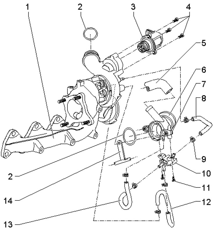
5.14a. Turbocharger connections (petrol models 1.4 l) 1. Turbocharger with exhaust manifold, vacuum block is secured to turbocharger with bolts with 20 Nm force, and vacuum block rod lock nut is tightened with 10 Nm force; 2. Sealing ring, subject to replacement; 3. Valve "N249" of air bleed of turbocharger; 4. Bolt, 11 Nm; 5, 8. Connecting hose; 6. Inlet pipe; 7, 11. Bolt, 10 Nm; 9. Spring band clamp; 10. Solenoid valve "N75" for boost pressure regulation; 12,13. Connecting hose; 14. Bracket, on the coolant line
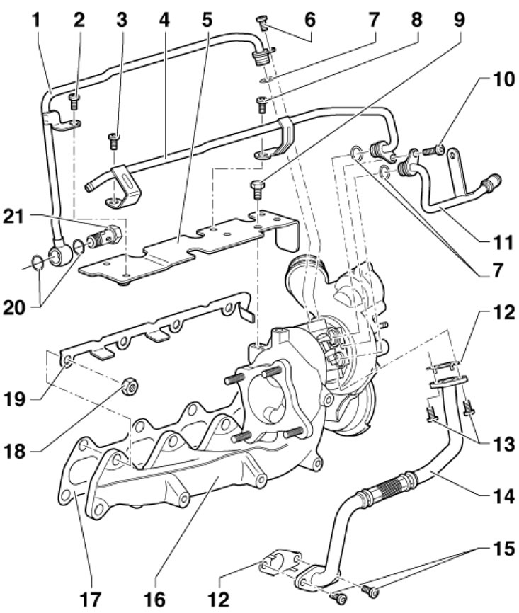
5.14b. Turbocharger connections and installation details (petrol models 1.4 l) 1. Oil supply 12, tube; 2, 3, 6. Bolt, 8 Nm; 4, 11. Coolant pipe; 5.19. Bracket; 7, 20. Sealing ring, subject to replacement; 8, 13, 15. Bolt, 8 Nm; 9. Bolt, 9 Nm; 10. Bolt, 11 Nm; 12, 17. Gasket, subject to replacement; 14. Return oil pipe; 16. Turbocharger with exhaust manifold; 18. Nut, subject to replacement, 16 Nm; 21. Hollow bolt, subject to replacement, 20 Nm
Petrol models 1.8 l: removal and installation of turbocharger
21. Turbocharger installation details are shown in the illustrations. The turbocharger is removed and replaced only as a complete assembly with the exhaust manifold and vacuum block.
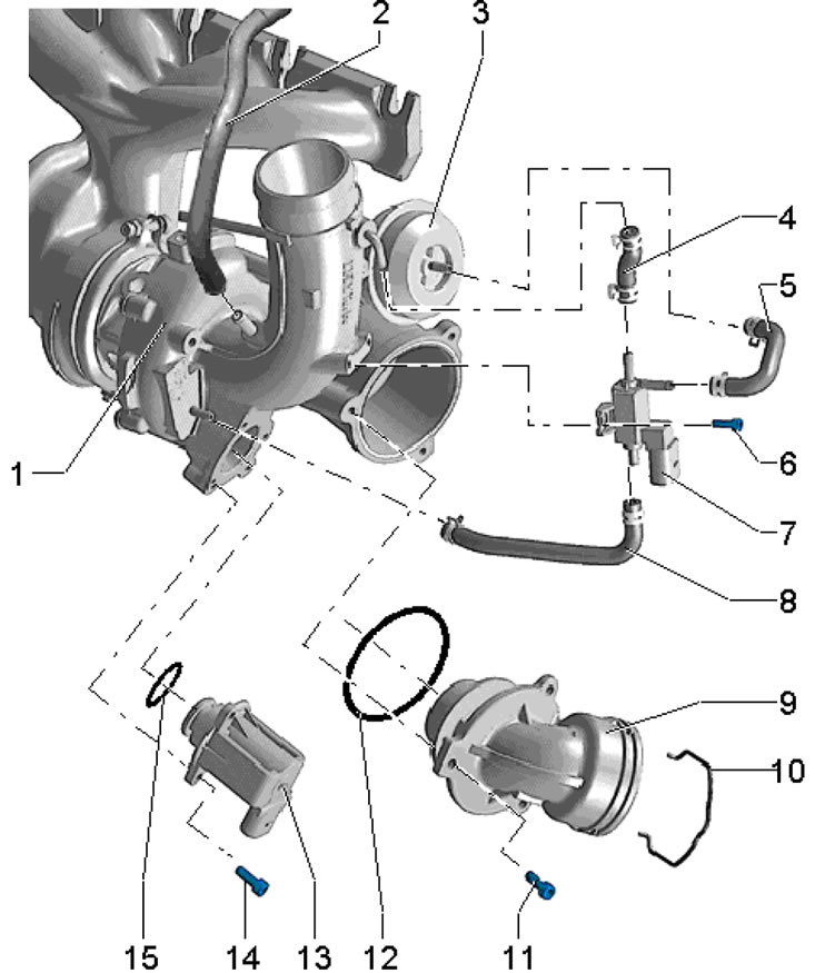
5.21a. Turbocharger hoses and solenoid valves (1.8 l models) 1. Turbocharger; 2. To the intake manifold; 3. Turbocharger vacuum block; 4, 5, 8. Hose; 6. Bolt, 3 Nm; 7. Solenoid valve "N75" for boost pressure regulation; 9. Connection; 10. Retainer; 11. Bolt, 9 Nm; 12, 15. Sealing ring, subject to replacement; 13. Valve "N249" of air bleed of turbocharger; 14. Bolt, 7 Nm
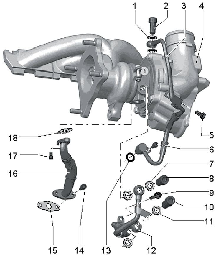
5.21b. Turbocharger pipes (1.8 l models) 1, 7, 11. Sealing ring, subject to replacement; 2, 8, 10. Hollow bolt, 20 Nm, then tighten to an angle of 45°; 3. Oil supply pipe; 4. Turbocharger; 5, 6, 9. Bolt, 9 Nm; 12. Coolant supply pipe; 13. Sealing ring, subject to replacement; 14, 17. Bolt, 9 Nm; 15, 18. Gasket, subject to replacement; 16. Return oil pipe
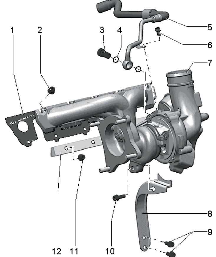
5.21c. Fasteners and return pipe of coolant of turbocharger (1.8 l models) 1. Gasket, subject to replacement; 2. Nut, must be replaced, before tightening, lubricate the studs with high-temperature grease G052 112A3; 3. Hollow bolt, 20 Nm, then tighten to an angle of 45°; 4. Sealing ring, subject to replacement; 5. Coolant return pipe; 6. Bolt, 9 Nm; 7. Turbocharger; 8. Bracket; 9, 10. Bolt, 30 Nm, lubricate the threads with high-temperature grease G052 112A3 before tightening; 11. Nut, do not loosen when removing the turbocharger, must be replaced, 30 Nm, before tightening, lubricate the studs with high-temperature grease G052 112A3; 12. Fastening strip
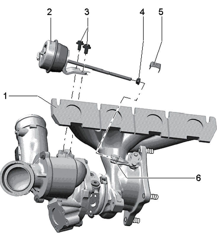
5.21d. Turbocharger vacuum block (1.8 l models) 1. Turbocharger; 2. Vacuum block; 3. Bolt, 10 Nm; 4. Nut, 9 Nm, sealed; 5. Locking plate; 6. Knurled nut
22. Drain the coolant (see Chapter 3).
23. Remove the right front wheel arch liner (see Chapter 11).
24. Remove the exhaust pipe (see Part B).
25. Remove the bolts (arrows in illustration 25.4 Chapter 2), lift the clamps (1 and 2) and remove the air pressure tube.
26. Remove the drive shaft cover bolts (see illustration 30.11 Chapter 2).
27. Disconnect the connectors (1 and 2 in Illustration 30.9 Chapter 2) and release the electrical wiring from the holders (arrows).
28. On models with additional heating, unscrew the bolts (1 and 2 in Illustration 30.10 Chapter 2) and turn the coolant pipes to the left.
29. Remove the bolts (1 and 2 in Illustration 30.12 Chapter 2) and remove the turbocharger bracket.
30. Unscrew the hollow bolt (2 in illustration 30.13 Chapter 2) and put the coolant line aside. Remove the return oil line bolts on the cylinder block and the supply oil line bolt (3).
Note: For clarity, the engine is shown removed in the illustration.
31. Remove the PCV tube (1 in illustration 23.2 Chapter 2), unscrew the bolts (arrows) and remove the intake manifold by loosening the clamp (2). Seal the turbocharger connection to prevent dirt from getting into it.
32. Disconnect the ignition coil connectors (see Section 14 Chapter 1) and put the wiring aside.
33. Disconnect the coolant line going to the expansion tank (see illustration 30.16 Chapter 2).
34. Disconnect the vacuum line (1 in the illustration) at the connection point (2) and release it from the holders. Disconnect the coolant hoses (arrows) from the coolant pipe, disconnect the ground wire (3) and unscrew the bolt (4).
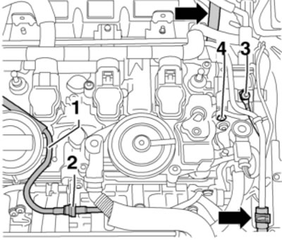
5.34. Vacuum line, coolant hose and ground wire connections
35. Remove the bolts (1-3 in illustration 30.19 Chapter 2) and remove the heat shield together with the coolant pipe.
36. Disconnect the coolant hose (see illustration 30.20 Chapter 2) and release it from the holder.
37. Give me the nuts (see illustration) and remove the turbocharger and exhaust manifold assembly upwards.
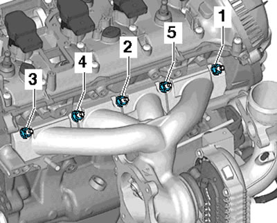
5.37. Turbocharger assembly fastening nuts
59. Installation is carried out in reverse order. Use new sealing elements and self-locking nuts. Tighten the turbocharger assembly mounting nuts in the following sequence: (1-5 in illustration 5.37) in 4 stages: 5 Nm, 12 Nm, 16 Nm, 25 Nm. Before connecting the feed oil pipe, fill the turbocharger with engine oil through the connection port of this pipe. The coolant return line is installed together with the turbocharger. After the engine is started for the first time, let it run for about a minute at idle speed.
1.8L Petrol Engines: Checking and Replacing the Vacuum Block
60. Make sure that the turbocharger hoses and the N75 boost pressure control solenoid valve are not clogged or leaking, and that the N75 valve is in good working order. The engine must be warmed up to a temperature of at least 60°C.
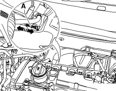
61. Start the engine and monitor the thrust (And in the illustration) vacuum block, using a mirror for this purpose. Ask your assistant to increase the engine speed by pressing the gas pedal sharply - the thrust should shift.
5.61. Vacuum block thrust
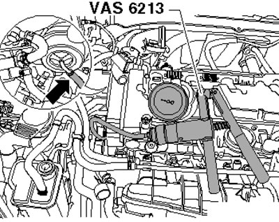
62. If the rod does not move when the speed increases, connect the VAS6213 hand vacuum pump to the vacuum block as shown in the illustration. Move the sliding ring at the vacuum pump nipple towards the pressure gauge.
5.62. Vacuum block hose
63. When working with a vacuum pump, watch the draft (And in illustration 5.61) vacuum block: at a pressure of approximately 300 mbar the rod should start moving, and at approximately 700 mbar it should reach the end of the adjustment stroke (10 mm).
Caution: Do not create pressure greater than 750 mbar to avoid damaging the vacuum unit. If pressure is not achieved and drops suddenly, replace the vacuum unit as described below. If pressure is created but the rod does not move, check the smooth movement of the bypass valve lever: if the lever is found to be blocked or stuck, the vacuum unit should also be replaced.
64. Remove the turbocharger (see subsection above).
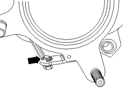
65. Remove the lock washer above the rod on the turbocharger (1 in the illustration).
5.65. Thrust lock washer
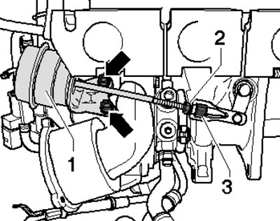
66. Loosen the locknut (2 in the illustration), separate the rod from the turbocharger (3), unscrew the bolts (arrows) and remove the vacuum block (1).
5.66. Fastening the vacuum block
67. Installation is carried out in reverse order. After disconnecting the rod, the vacuum block should be adjusted.
1.8L Petrol Engines: Vacuum Block Adjustment
Note: Adjustment of the vacuum block is required only after disconnecting its rod and is performed with the turbocharger removed.
68. Remove the turbocharger (see subsection above).
69. Disconnect the hose from the vacuum unit (see illustration).
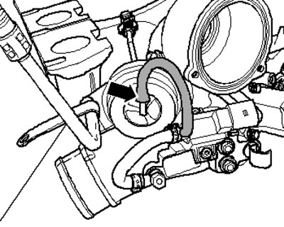
5.69. Hose connection on the vacuum block
70. Remove the lock washer above the rod on the turbocharger (1 in illustration 5.65) and loosen the lock nut (2 in illustration 5.66).
71. Pre-install the bypass valve (1 in the illustration) above the vacuum block rod (arrow) so that the valve can still be turned manually.
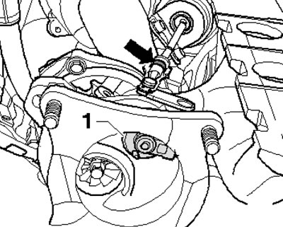
5.71 Preliminary installation of the bypass valve
72. Assemble the vacuum pump VAS6213, tester VAG1397A and pressure test valve VAS6342 as shown in the illustration. Connect the VAS6342 valve to the lever (1). Move the sliding ring at the vacuum pump connection towards the pressure gauge. Turn on the VAG1397A tester and move its switch to the "II" position.
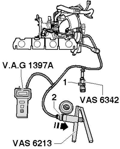
5.72. Control devices
73. Attach the MP3-447 holder to the turbocharger (arrow on the illustration). Attach the VAS6341/1 indicator with the 30 mm extension VAS6341 /3 and the flat nut AVS6341 /4 to the holder. At zero pressure, set the preload on the indicator to 1 mm and then reset it to zero. Check the smoothness of its indicator movement.
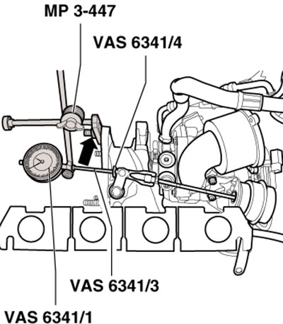
5.73. Installing the indicator
74. Using a vacuum pump, create a pressure of 460±5 mbar (according to VAG 1397 tester). The indicator should show 4.1-4.3 mm. Otherwise, turn the vacuum block rod until this size is reached.
75. Tighten the lock nut by hand and repeat the measurement. Release the pressure via the check valve to 0 bar and reset the indicator.
76. Using the vacuum pump, create a pressure of 460±5 mbar again (according to VAG 1397 tester) and record the indicator reading (this will be considered value #1). Then, increase the pressure to 650-700 mbar and drop it to 460±5 mbar. Record the indicator reading again (this will be considered value #2). Add values #1 and #2, then divide them by 2. The result should be 5±0.25 mm. Otherwise, adjust the position of the rod, tighten the lock nut by hand and repeat the adjustment.
77. When the value specified in paragraph 76 is reached, tighten the lock nut to 9 Nm and secure with paint. Install the lock washer over the vacuum block rod.
Diesel engines 2.0 l (CFHC, CFJA and CLCB)
78. Turbocharger installation details are shown in the illustrations. The turbocharger is removed and replaced only as a complete assembly with the exhaust manifold and vacuum block.
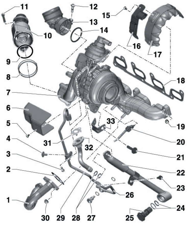
5.78a. Turbocharger installation details (engines 2.0 l CFHC, CLCB) 1. Connecting pipe, to EGR radiator; 2, 18, 31. Gasket, subject to replacement; 3. Bolt, 20 Nm, subject to replacement; 4. Bolt on bracket 33, 10 Nm; 5, 15. Bolt, 15 Nm; 6, 17. Heat shield; 7. Turbocharger; 8. Retaining ring; 9, 14. Sealing ring, subject to replacement; 10. Pulsation damper; 11, 12. Bolt, 9 Nm; 13. Inlet connection; 16. Electrical wiring bracket; 19. Nut, subject to replacement, 24 Nm; 20. Sensor No. 1 "G235" exhaust gas temperature (upstream sensor "G507" turbocharger temperature), 45 Nm; 21. Bolt, 20 Nm; 22. Turbocharger support; 23. Bolt, 10 Nm; 24, 28. Sealing rings of different diameters are subject to replacement; 25. Hollow bolt, 60 Nm, subject to replacement; 26, 29. Oil supply line, tighten union nuts to 22 Nm; 27. Hollow bolt, 30 Nm, subject to replacement; 30. Nut, 24 Nm; 32. Return oil line; 33. Oil supply line bracket
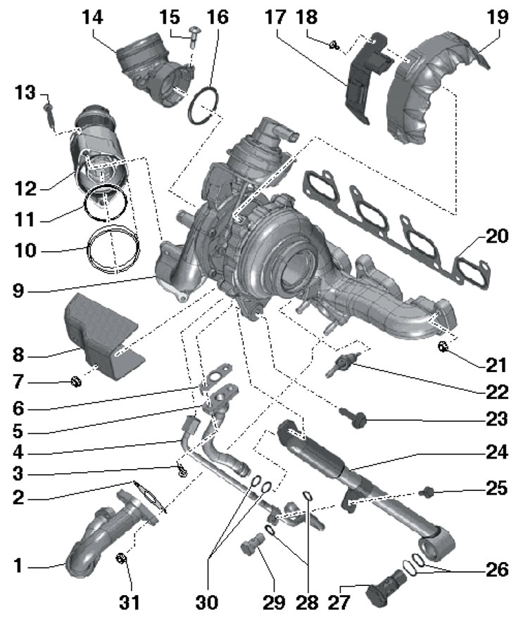
5.78b. Turbocharger installation details (2.0 CFJA engine) 1. Connecting pipe, to EGR radiator; 2, 6, 20. Gasket, subject to replacement; 3. Bolt, 17 Nm, subject to replacement; 4. Oil supply line, tighten union nuts to 22 Nm; 5. Return oil line; 7, 31. Nut, 24 Nm; 8. Heat shield; 9. Turbocharger; 10. Retaining ring; 11, 16. Sealing ring, subject to replacement; 12. Pulsation damper; 13. Bolt, 9 Nm; 14. Inlet connection; 15. Captive bolt, 9 Nm; 17. Electrical wiring bracket; 18. Bolt, 15 Nm; 19. Heat shield; 21. Nut, subject to replacement, 24 Nm; 22. Sensor No. 1 "G235" exhaust gas temperature (upstream sensor "G507" turbocharger temperature), 45 Nm; 23. Bolt, 20 Nm; 24. Turbocharger support; 25. Bolt, 10 Nm; 26. Sealing rings of different diameters are subject to replacement; 27. Hollow bolt, 60 Nm, subject to replacement; 28, 30. Sealing rings, subject to replacement; 29. Hollow bolt, 30 Nm