
Company vehicles Hyundai Company vehicles Kia Company vehicles Lada Company vehicles Mazda Company vehicles Mercedes-Benz Company vehicles Opel Company vehicles Mitsubishi
English Русский
Български
Беларускі
Український
Српски
Hrvatski
Română
Polski
Slovenský
Magyar
Articles   
Bookmark Contacts Sitemap
SkodaBook.ru


Fabia Rapid Octavia Superb Kodiaq Yeti Others
Yeti (2009-2017)

Removal and installation the accessory drive belt and auxiliary brackets (Skoda Yeti 5L)

  • Main
  • Yeti
  • 5L (2009-2017)
  • Power unit
  • Petrol engine 1.2 l
  • Removal and installation the accessory drive belt and auxiliary brackets
0
Contents: Drive belt ⬇ Upper auxiliary bracket ⬇ Lower auxiliary bracket ⬇
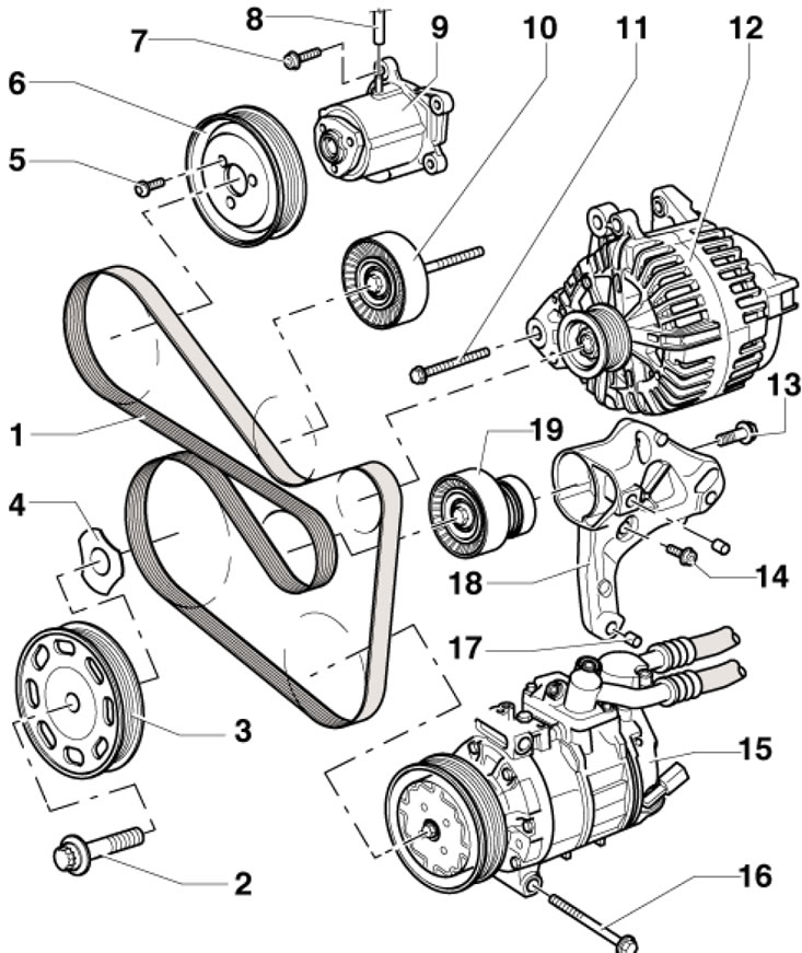
1. The installation details of auxiliary units are shown in the illustration.

6.1. Installation details of auxiliary units…

6.1. Installation details of auxiliary units (using the example of models with a refrigeration unit) 1. Drive belt; 2. Pulley bolt 3, subject to replacement, when screwing in, the thread must be lubricated, but the supporting surface must not; 3. Crankshaft pulley; 4. Diamond coated washer, replaceable; 5. Bolt, 20 Nm; 6. Pump pulley 9; 7. Bolt, 9 Nm; 8. Vacuum hose, to the solenoid valve of the cooling circuit on the intake manifold; 9. Water pump; 10. Intermediate roller, 40 Nm; 11, 14,16. Bolt, 25 Nm; 12. Generator; 13. Bolt, subject to replacement, 40 Nm, then tighten to an angle of 90°; 15. Air conditioning compressor; 17. Centering sleeve; 18. Auxiliary units bracket; 19. Belt tensioner 2


Drive belt


2. Remove the sound insulation under the engine compartment (see Chapter 11).

3. If the belt being removed is intended to be reused, mark the direction of its movement on it.

4. Pull the belt tensioner with a 16 mm wrench in the direction of the arrow (see illustration), to loosen the belt, then lock the tensioner by inserting a 4 mm open-end wrench (1).
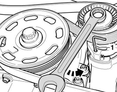


6.4. Fixing the drive belt tensioner

6.4. Fixing the drive belt tensioner


5. Remove the drive belt. If necessary, unscrew the bolt and remove the belt tensioner.

6. Installation is carried out in reverse order. First, place the belt on the crankshaft pulley and finish installing the belt on the tension roller. If a used belt is being installed, the marks on it must face the direction of its rotation when the engine is running. Make sure the belt is seated correctly on the pulleys. The belt routing diagram is shown in illustrations 6.6a, b.
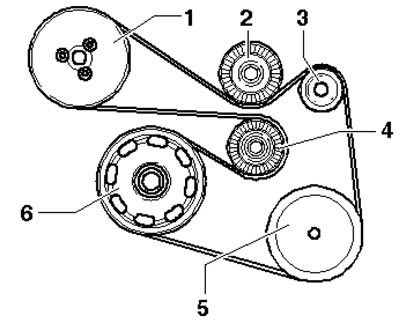
6.6a. Drive belt routing diagram (models with…

6.6a. Drive belt routing diagram (models with refrigeration unit) 1. Water pump pulley; 2. Intermediate roller; 3. Generator pulley; 4. Tension roller; 5. Compressor pulley; 6. Crankshaft pulley
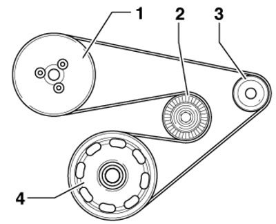

6.6b. Drive belt routing diagram (models without…

6.6b. Drive belt routing diagram (models without refrigeration unit) 1. Water pump pulley; 2. Tension roller; 3. Generator pulley; 4. Crankshaft pulley


Upper auxiliary bracket


7. Remove the accessory drive belt (see subsection above).

8. Remove the generator (see Chapter 5).

9. Drain the coolant (see Chapter 3).

10. Remove the lambda probe (1 in the illustration).
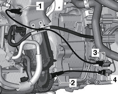
6.10. Lambda probes and their connectors

6.10. Lambda probes and their connectors


11. Remove the bolts (arrows in the illustration) and remove the heat shield (1).
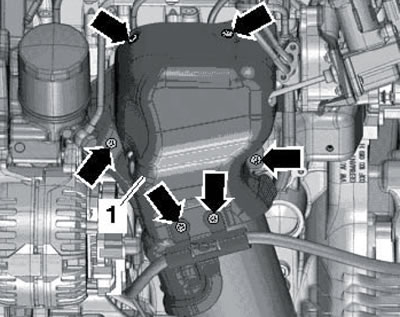
6.11. Heat shield bolts

6.11. Heat shield bolts


12. Open the clamp (1 in the illustration) and disconnect the coolant hose. Remove the hollow bolt (2) and the mounting bolt (3), and then remove the oil feed line, preventing oil from getting on the generator.
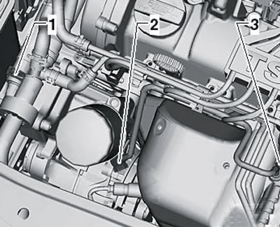
6.12. Coolant hose and oil feed pipe

6.12. Coolant hose and oil feed pipe


13. Remove the bolts (1 in the illustration) and remove the bracket.
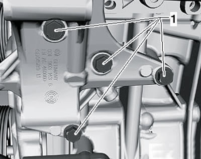
6.13. Upper bracket fastening

6.13. Upper bracket fastening


14. Installation is carried out in reverse order. Tighten the bracket mounting bolts to 25 Nm. Tighten the hollow bolt of the oil pipe to 20 Nm, and the bolt that mounts it on the turbocharger to 8 Nm.

Lower auxiliary bracket


15. Remove the accessory drive belt (see subsection above) and generator (see Chapter 5).

16. Remove the air conditioning compressor (see Chapter 3), without disconnecting the refrigerant lines from it, and secure it to the hood lock holder with wire so that the refrigerant lines are not deformed.

17. Remove the bolts (see illustration) and remove the bracket.
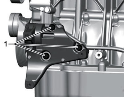
6.17. Bottom bracket fastener

6.17. Bottom bracket fastener


18. Installation is carried out in reverse order. Tighten the bracket mounting bolts to 25 Nm.
This article is available at russian, bulgarian, belarusian, ukrainian, serbian, croatian, romanian, polish, slovak, hungarian
Article verified: Timur Komissarov
Share with friends:
◀ Previous
Skoda Yeti: Petrol engine 1.2 l
Next ►

Removal and installation of the engine and its supports
Checking engine oil pressure and the corresponding sensor
Checking the engine with a vacuum gauge
Checking the compression pressure
General information and preparatory operations
Removal and installation timing belt covers
Replacing crankshaft seals, removing and installing flywheel and…
Removal and installation the cylinder head, its cover and camshaft
Checking and adjusting the timing phases (setting TDC)
Removal and installation the timing chain and oil pump drive chain
Read similar articles on other Skoda models

➧ Replacing the alternator drive belt Skoda Fabia 1 (1999-2007)
➧ Accessory Drive Belt — External View Skoda Rapid 1 (2012-2022)
➧ Toothed belt drive — parts and components Skoda Octavia 3 (2013-2019)
➧ Removal and installation the auxiliary bracket and accessory drive… Skoda Superb 2 (2008-2015)
➧ Poly V-belt for accessory drive Skoda Kodiaq 1 (2016-2024)
➧ Checking the condition of the auxiliary drive belt Skoda Felicia (1994-2001)
Link to this article in various formats
Reviews and comments of visitors
No comments yet


Add two numbers: 35 + 31


Yeti (2009-2017) 
  • General information
  • Introduction to manual
  • Controls and instruments
  • Maintenance
  • Power unit
  • Petrol engine 1.2 l
  • Petrol engine 1.4 l
  • Petrol engine 1.8 l
  • Diesel engine 2.0 l
  • Cooling system
  • Power and control system
  • Exhaust system
  • Ignition and preheating systems
  • Starting and charging system
  • Transmission
  • Clutch
  • Manual gearbox
  • 7-speed gearbox DSG «0AM»
  • 6-speed gearbox DSG «02E»
  • Drive shafts
  • Chassis (running gear)
  • Brake system
  • Front suspension
  • Rear suspension
  • Steering
  • Body and interior
  • Heating and air conditioning
  • Exterior (external elements)
  • Interior (internal elements)
  • Electrical equipment
  • Equipment and devices
  • Lighting and signaling
  • Electrical diagrams
SkodaBook.ru © 2018–2026 | Mobile version | Articles on Skoda | Sitemap EN BG BY UA RS HR RO PL SK HU | Feedback | Site search | Bookmark
Fabia 1 (1999-2007) | Fabia 2 (2007-2014) | Rapid 1 (2012-2022) | Octavia 1 (1996-2004) | Octavia 3 (2013-2019) | Superb 2 (2008-2015) | Kodiaq 1 (2016-2024) | Yeti (2009-2017) | Favorit (1987-1994) | Felicia (1994-2001) |
By continuing to use the site, you agree to the use of cookies.