



Removal
Note: The engine is removed downwards together with the transmission. All removed electrical wiring ties and clamps must be installed in their original places during installation. The electrical wiring and hoses should be routed in the same way as they were before removal. Therefore, you should remember or sketch the location of the clamps, electrical wiring and hoses.
1. Relieve the pressure in the fuel supply system and remove the air cleaner (see Chapter 4).
2. Remove the battery and its holder (see Chapter 5).
3. Remove the wheel arch liners from both front wheels and the sound insulation under the engine compartment (see Chapter 11).
4. Drain the coolant (see Chapter 3).
5. Remove the right drive shaft (see Chapter 8).
6. Remove the left drive shaft mounting bolts (1 in the illustration) to the transmission flange shaft. Loosen the nut of the left stabilizer bar (2) and press it away from the stabilizer. Then remove the three nuts (3) of the ball joint and separate it from the suspension arm.
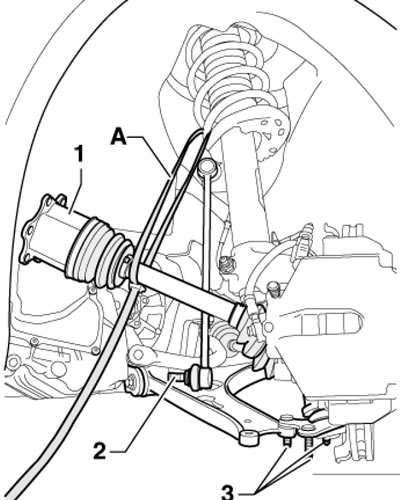
5.6. Fixing the left drive shaft to the suspension strut
7. If there is a suspension height sensor, loosen the nut (2 in the illustration) its attachment to the lever. Turn the steering wheel all the way to the left, pull the ball joint outward and, using a suitable strap, (And in illustration 5.6) secure the left drive shaft to the suspension strut to prevent the CV joint from bending too much. Insert a pin into the control arm to stabilize the ball joint.
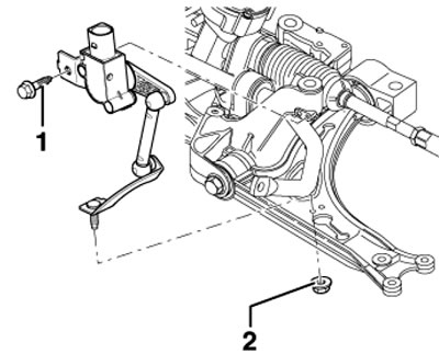
5.7. Nut (2) for fastening the suspension level sensor
8. Disconnect the upper part from the expansion tank (2 in the illustration) and the lower coolant hoses. Disconnect the fuel supply line (3) by pressing the retaining ring upwards and collect the leaking fuel with a cloth. Disconnect the connecting hose (4) going to the EVAP canister.
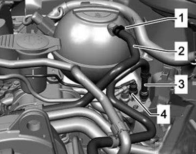
5.8. Coolant hose (2) and fuel system lines (3 and 4)
9. Remove the hose (1 in the illustration) from the EVAP canister and from the canister purge valve. Remove the adsorber (2), loosen the clamp (4) and disconnect the coolant hose (3) from the engine.
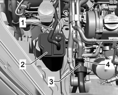
5.9. EVAP canister hose (2) (1) and coolant hose (3)
10. Pull out the clamps (see illustration) and disconnect the coolant hoses from the heater radiator.
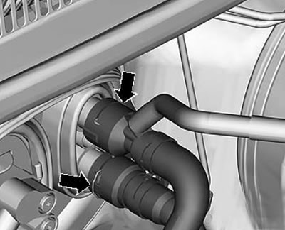
5.10. Connections of coolant hoses to the heater radiator
11. Disconnect the vacuum hose from the intake manifold (1 in the illustration), loosen the clamps (2) and disconnect the coolant hoses (3-5).
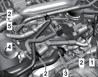
5.11. Vacuum hose (1) and coolant hoses (3-5)
12. On models with DSG, remove the selector cable from it (see Chapter 7).
13. On models with a manual transmission, remove the gear shift mechanism and hydraulic clutch drive components from it (see chapter 6).
Note: After removing the clutch slave cylinder or disconnecting the clutch line, do not depress the clutch pedal.
14. Disconnect all electrical wiring from the transmission, generator and starter, then release it along with the rest of the wires from the holders on the engine.
15. Disconnect the vacuum and ventilation hoses from the engine, disconnect the connector of the thermal switch and the radiator fan. Disconnect the engine wiring harness connector at the ECM (front connector, see Chapter 5). Remove the wiring harness guide plate clamp (see illustration) and pull it up from the bulkhead near the expansion tank.
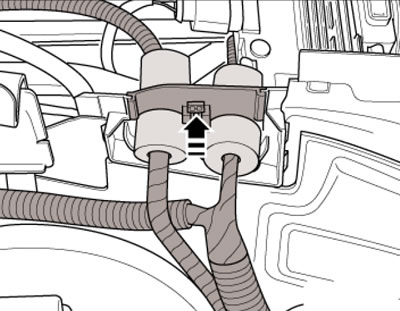
5.15. Wiring guide plate retainer
16. Open all the protection of the engine wiring harness on the side member (see illustration). Open the other connections of the engine wiring harness, remove it, place it on the engine and secure it with clamps.
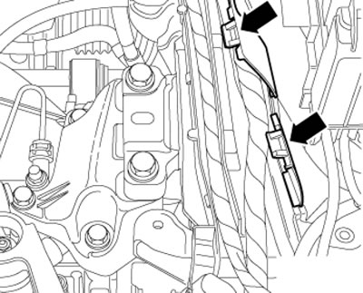
5.16. Protection of electrical wiring harnesses
17. Disconnect the connectors (1 and 2 in the illustration) and remove the front exhaust pipe (see Chapter 4, Part B).
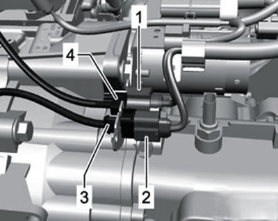
5.17. Connectors above the transmission
18. Unscrew the bolt (2 in the illustration) and remove the lower coolant pipe (1). On models with an additional heater, loosen the clamps (3) and disconnect the coolant hoses (4 and 5).
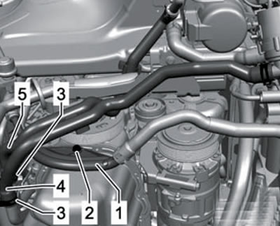
5.18. Coolant pipe (1) and hoses (4 and 5)
19. On models with additional heating, unscrew the bolts (1 and 2 in the illustration) coolant pipe brackets (3).
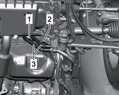
5.19. Fastening the coolant pipes of the additional heater
20. Disconnect the connector (2 in the illustration) engine oil level and temperature sensor. Remove the sensor wiring guide bracket from the front of the powertrain mount and lower it onto the powertrain mount.
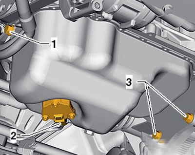
5.20. Engine oil level and temperature sensor (2)
21. Loosen the swing support fasteners in the following sequence: (1-3 in the illustration) and remove it. On models with a refrigeration unit, remove the accessory drive belt (see section 6).
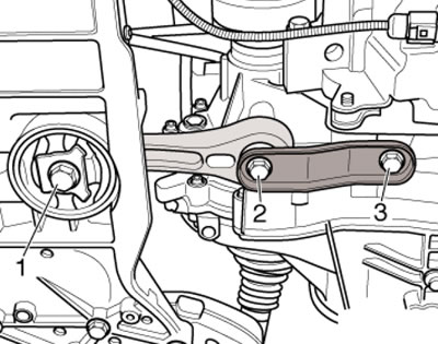
5.21. Fastening of the swing support
22. On models with a refrigeration unit, disconnect the connector (1 in the illustration) compressor magnetic clutch and unscrew the bolts (arrows). Remove the air conditioning compressor without disconnecting the refrigerant lines from it and secure it to the hood lock holder with wire so that the refrigerant lines are not stretched or kinked.
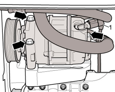
5.22. Connector (1) and fasteners (arrows) of the refrigeration unit compressor
23. To lower the power unit, prepare the T10416 support with adapters T10416/1, T10416/2 and T10416/3 (see illustration).
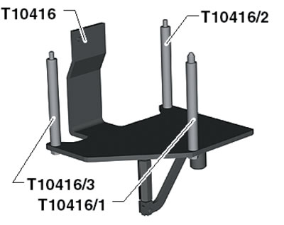
5.23. Device for removing the power unit
24. Screw the T10416/1 adapter into the cylinder block until it stops (see illustration).
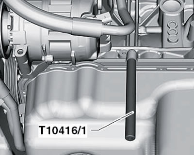
5.24. Adapter T10416/1
25. Place the T10416 support with the T10416/2 and T10416/3 adapters on the cylinder block and secure it by tightening the bolt (1 in the illustration) by hand. Tighten all support mounting bolts with a force of 20 Nm, install a VAG1383A jack under the support and slightly lift the power unit on it to relieve its supports. The correct angle between the support pin and the jack is set by the regulator (2).
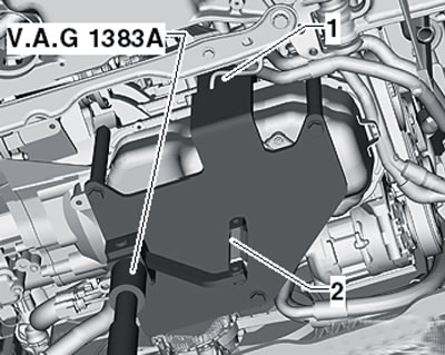
5.25. Installing the jack
26. Make sure all hoses and wiring between the engine, transmission and body are disconnected. Take the bolts from the stepladder (2 on accompanying illustrations) fastening the right and left brackets (on the engine and transmission).
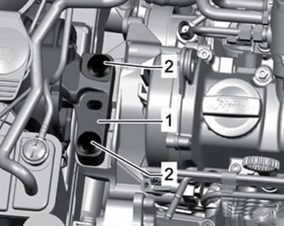
5.26a. Right bracket bolts (on the engine)
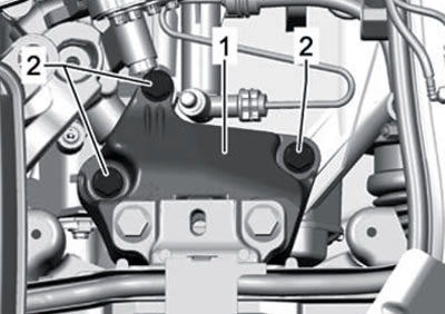
5.26b. Left bracket bolts (on the transmission)
27. Together with an assistant, pull the power unit as far forward as possible and carefully lower it from the engine compartment using a jack. Avoid damaging powertrain components and engine compartment components.
28. Separate the transmission from the engine (see chapter 6 or 7) and fix it on the mounting stand.
Installation
Note: Place the hoses and wiring in the same position as they were before removal; install all clamps and ties back in their original places. Depending on the thread, tighten the fasteners with the following forces: M6 - 10 Nm, M7 - 13 Nm, M8 - 20 Nm, M10 - 45 Nm, M12 - 60 Nm.
29. Installation is carried out in reverse order. Please note the following features.
30. Use new self-locking nuts and bolts that require tightening to a certain angle. Use new seals and gaskets.
31. On models with manual transmission, clean the splines of the transmission input shaft and, if an old clutch disc is used, its splines. Remove any traces of corrosion and apply a very thin coat of G000 100 grease to the input shaft splines. Move the clutch disc on the shaft until the disc moves smoothly, then remove any excess grease. Check the clutch release bearing for wear; replace it if necessary. Make sure the clutch is centered (see Chapter 6).
32. Make sure the transmission centering bushings are inserted into the cylinder block. Secure the transmission to the engine (see chapter 6 or 7).
33. Secure the power unit to the transmission jack using the T10416 support, move it into the engine compartment and screw in the new power unit bracket mounting bolts by hand. Adjust the brackets and tighten the bolts that secure them (see subsection below).
34. Install the rocker support (see subsection below) and drive shafts (see Chapter 8).
35. On models with refrigeration, install the compressor and accessory drive belt.
36. On models with manual transmission, install the clutch slave cylinder and gear shift mechanism.
37. On models with DSG, secure the selector cable.
38. Place the engine wiring harness and connect it to the ECM.
39. Install the front exhaust pipe.
40. Check and, if necessary, adjust the engine oil level.
41. Fill the engine cooling system (see Chapter 3).
42. Clear all fault codes from the ECM memory that occurred during engine removal/installation and verify that the ECM has generated a readiness code.
43. Perform a road check (see Chapter 1) and fix any errors found.
Checking and adjusting the powertrain supports
44. The details of the support fastenings are shown in the illustration.
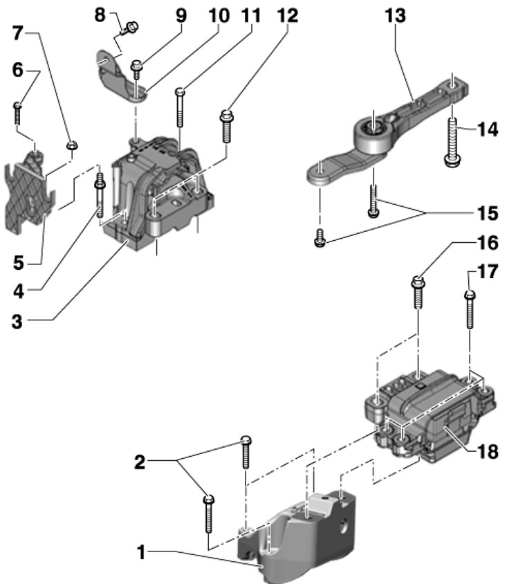
5.44. Powertrain support fastening parts 1. Transmission support bracket; 2. Bolt; 3. Engine support; 4. Stud bolt, to be replaced, 40 Nm, then tighten to an angle of 90°; 5. EVAP canister bracket; 6. Bolt, 9 Nm; 7. Nut, 9 Nm; 8.9. Bolt, subject to replacement, 20 Nm, then tighten to an angle of 90°; 10. Connecting piece; 11, 17. Bolt, subject to replacement, 40 Nm then tighten to an angle of 90°; 12.16. Bolt, subject to replacement, 60 Nm then tighten to an angle of 90°; 13. Swing support, when removing, unscrew the bolts in the sequence 14-15, and when installing - in the sequence 15-14; 14. Bolt, subject to replacement, 100 Nm, then tighten to an angle of 90°; 15. Bolts, subject to replacement, 40 Nm (strength class 8.8) or 50 Nm (strength class 10.9), then pull it to a 90° angle; 18. Transmission support
45. To check the installation of the bracket, measure the distance (and on the accompanying illustrations) between the bracket and the support, - it should be 10 mm. The cast edge of the support (2) should be parallel to the support lever (1), i.e. the distance (x) should be the same at the front and back. If the engine or transmission hits the side member when turning and the distance (a) is not 10 mm, adjust the bracket as described below.
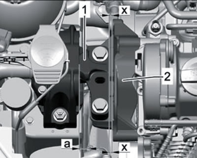
5.45. Checking the installation of the right bracket
46. Remove the battery and its holder (see Chapter 5).
47. Remove the expansion tank cap.
48. Install support T30099 (see illustration) and evenly relieve the power unit supports by rotating both spindles.
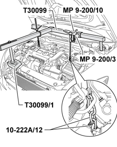
5.48. Unloading the power unit supports
Note: The illustration is given using a 1.4 l engine as an example.
49. Loosen the bolts (2 in illustration 5.26a) fastening the right bracket and slightly (no more than 1 turn) loosen the bolts (2 in illustration 5.26b) fastening the left bracket.
50. If the bracket bolts were not yet replaced when installing the engine, screw in the new bolts one by one.
51. Move the power unit using a lever installed between the support lever (1 in illustration 5.45) and support (2) so that the distance (a) is 10 mm and the distance (x) is the same at the front and back. Tighten the right support bolts (see illustration 5.44).
52. Make sure that on the transmission side the edges of the support (1 in the illustration) and its support lever (2) are located parallel to each other. That is, the distance (x) must be the same on both sides of the support. Tighten the bracket mounting bolts (see illustration 5.44).
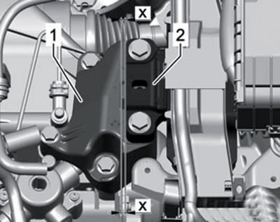
5.52. Checking the installation of the left bracket
53. Install the remaining parts.