



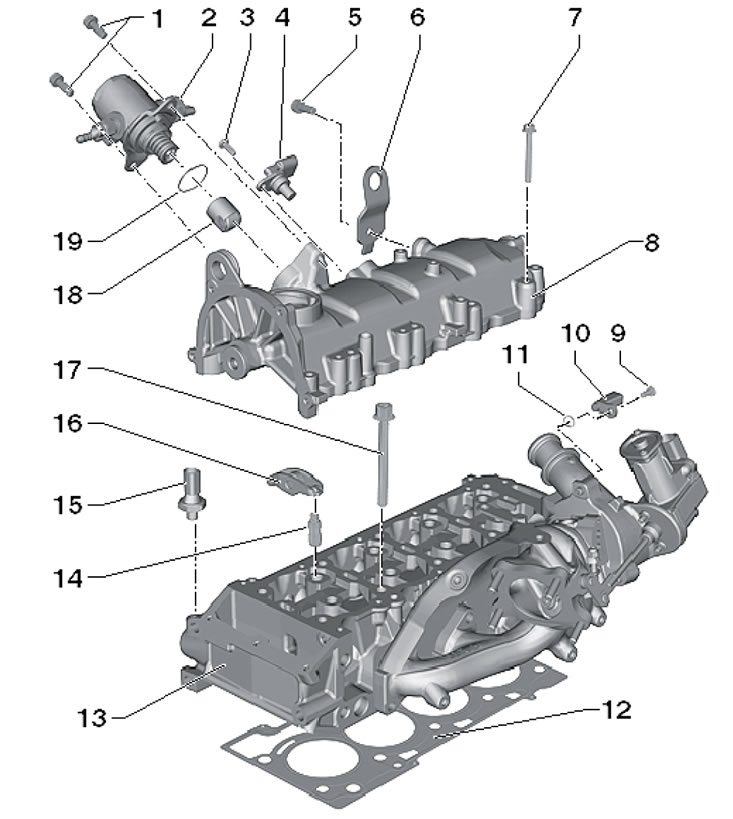
9.1. Cylinder head installation parts and components 1. Bolt, 8 Nm; 2. Fuel injection pump with valve "N276" for fuel pressure regulation; 3. Bolt, 10 Nm; 4. CMP sensor "G40", with sealing ring; 5. Bolt, 20 Nm; 6. Lifting eye; 7. Bolt, subject to replacement, 8 Nm, then tighten to an angle of 90°; 8. Cylinder head cover; 9. Bolt, 10 Nm; 10. Sensor ECT "G62"; 11, 19. Sealing ring, subject to replacement; 12. Metal cylinder head gasket, subject to replacement; 13. Cylinder head, mating surfaces should not be lubricated; 14. Valve lifter with hydraulic valve clearance compensation; 15. D/V "F1" low pressure engine oil, 20 Nm; 16. Rocker arm, fixed on pusher 14; 17. Cylinder head mounting bolt, subject to replacement; 18. Roller pusher
2. When installing a remanufactured cylinder head, all mating surfaces between tappets, rocker arms, cams and other rubbing surfaces must be lubricated before the cylinder head cover is installed. After removing the cylinder head, the coolant should be replaced.
Cylinder head cover and camshaft
3. Disconnect the negative cable from the battery.
4. Remove the sound insulation under the engine compartment (see Chapter 11).
5. Remove the upper timing belt cover (see Section 7).
6. On models with additional heating, unscrew the bolts (1 and 2 in Illustration 5.19) coolant pipe brackets (3).
7. Remove the bolts (1 in illustration 8.9) and remove the coolant pipe bracket (2).
8. Unscrew the service hole plug in the cylinder block and screw in the T10340 locking pin instead (see illustration 8.11) until it stops. This pin is designed to prevent the crankshaft from turning when tightening the bolt of its pulley.
9. If the locking pin cannot be screwed in all the way, the crankshaft is in the wrong position. In this case, follow these steps. Remove the locking pin, turn the crankshaft clockwise by 90°, screw the locking pin into the cylinder block until it stops, tighten it to 30 Nm, and then turn the crankshaft clockwise until it stops.
10. Disconnect both coolant hoses from the non-return valve (1 in the illustration), unscrew the bolt (2) and remove the valve from the cylinder head cover.
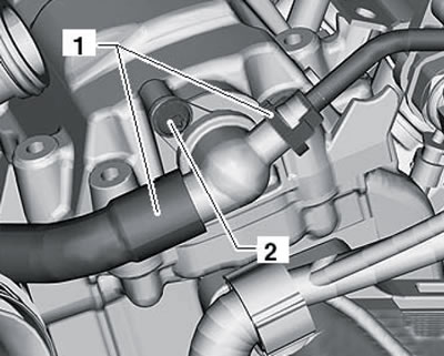
9.10. Non-return valve installation details
11. Insert the T10414 locking device into the cylinder head cover until it stops and tighten the bolt by hand (1 in the illustration).
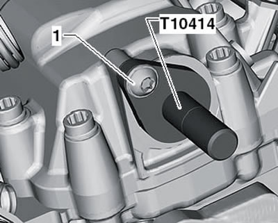
9.11. Installing the T10414 locking device
12. Remove the oil pan (see Section 13), and then remove the lid (1 in the illustration) oil pump.
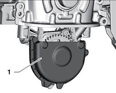
9.12. Oil pump cover
13. Loosen the timing chain tensioner (see illustration).
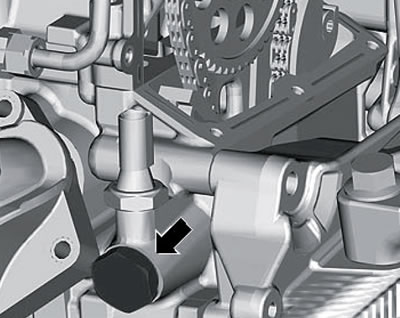
9.13. Timing chain tensioner
14. Holding the camshaft sprocket with tool T10172, remove the bolt (1 on the accompanying illustration) its fasteners and remove the sprocket.

9.14. Loosening the camshaft sprocket mounting bolt
15. Lay the timing chain (1 in the illustration) on the cast protrusion (arrow) inside the timing mechanism housing to prevent the chain from falling.
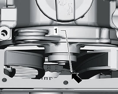
9.15. Timing chain fixation
16. Disconnect the air cleaner hose from the cylinder head cover. Remove the bolts (1 in the illustration) and remove the retaining clamp. Disconnect the connector (2) of the boost pressure sensor "G31", release the holders in the direction of the arrows and disconnect the pressure pipe (3) first from the throttle module and then from the turbocharger. Remove the plug and unscrew the bolt (4) located underneath. Disconnect all spark plug connectors and lay the wiring behind.
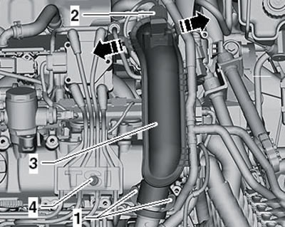
9.16. Removing the pressure tube
17. Remove the fuel injection pump (see Chapter 4), disconnect the injector wiring connectors, unscrew the bolts (see illustration) and remove the fuel rail from the injectors.
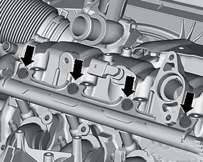
9.17. Fastening the fuel distribution line
18. Remove the turbocharger (see Chapter 4).
19. Disconnect the CMP sensor connector.
20. Remove the engine oil level dipstick from the guide tube.
21. Loosen the cylinder head cover mounting bolts one by one in a diagonal order (from external to internal) and carefully remove the cylinder head cover.
22. Cover the cylinder head to prevent dirt from getting into it.
23. If necessary, remove the camshaft. To do this, remove the locking device T10414, place the cylinder head cover with the camshaft facing up, and unscrew the bolts in the following sequence: (AJ in the illustration), remove the camshaft bed and the shaft itself.
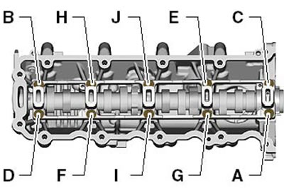
9.23. Sequence of unscrewing the camshaft bed bolts
24. If the camshaft has been removed, lightly lubricate the shaft and its bearings with engine oil. Lay the shaft (1 in the illustration) into the cylinder head cover (2), secure the T10414 locking device to the shaft and place its bed on the shaft, aligning it with the centering pins (arrows). Tighten the bed mounting bolts with a force of 8 Nm in the sequence (JA in illustration 9.23).
The original article is located on www.SKODABOOK.ru
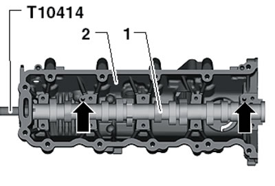
9.24. Device T10414 and centering pins of the camshaft bed
25. Make sure that none of the pistons are in the TDC position. Remove any remaining sealant from the cylinder head and its cover using a suitable chemical agent or a drill with a rotating plastic brush. Do not allow dirt or sealant residue to get into the cylinder head. Thoroughly clean the mating surface from oil and grease.
26. Screw two M6x70 studs into the cylinder head (1 in the illustration). The cylinder head cover is guided by these studs so that the rocker arms do not slip off the tappets.
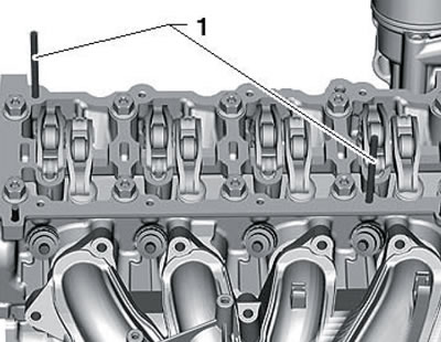
9.26. Centering pins
27. Apply an even bead of sealant D 189 500 A1 with a diameter of 2-3 mm around the perimeter (1 in the illustration) cylinder head covers. Then apply an even, thin layer of sealant D 154 103 A1 to the surfaces (2).
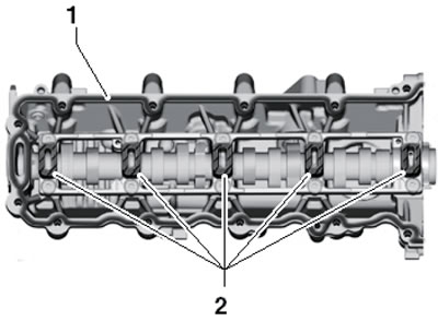
9.27. Sealant application diagram
Note: Different sealants are used on surfaces (1 and 2)! There should not be too much sealant, so that its excess does not squeeze out and get into the oil channels.
28. Make sure that all rocker arms are seated correctly on the pushrods and carefully place the cylinder head cover onto the guide pins. Tighten the new cylinder head cover bolts in the following sequence: (AL in the illustration) with a force of 8 Nm, and then pull them to an angle of 90°.
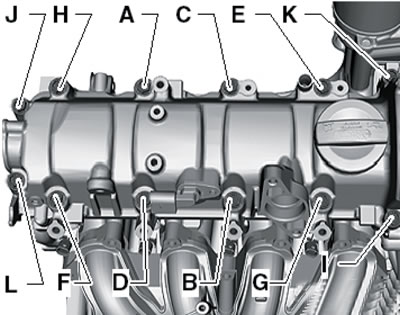
9.28. Cylinder head cover fastener tightening sequence
29. Remove the squeezed out sealant in the places shown in the illustration to prevent leaks from developing due to mixing different sealants (for cylinder head cover and for upper timing belt cover).

9.29. Sealant removal locations
30. Turn the crankshaft clockwise until it stops and lift the timing chain using the T10118 tool (see illustration).
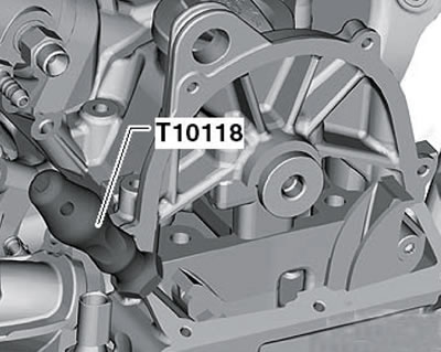
9.30. Device T10118
31. From underneath the vehicle, make sure the timing chain (1 in the illustration) is correctly positioned on the crankshaft sprocket.
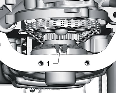
9.31. Timing chain position on the crankshaft sprocket
32. Lay the timing chain (1 in the illustration) on the sprocket (2) of the camshaft. The chain must make contact in the area of the guide bar (3) and must be slightly taut.
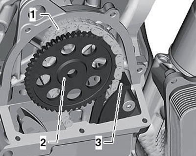
9.32. Installing the timing chain on the camshaft sprocket
33. While holding the camshaft sprocket from turning with the T10172 tool, tighten the new sprocket mounting bolt to 50 Nm (see illustration 9.14).
Note: The bolt should be finally tightened after checking the timing phases at the end of the installation.
34. Make sure the timing chain is centered in the tensioner bar and tighten the tensioner (see illustration 9.13) with a force of 60 Nm.
35. Remove the locking device T10414 from the camshaft, unscrew the locking pin T10340 from the cylinder block and turn the crankshaft two revolutions.
36. Screw the T10340 locking pin into the cylinder block until it stops and turn the crankshaft clockwise until it stops. The timing phases are set correctly if the locking device T10414 can be inserted into the camshaft. If this fails, repeat the timing adjustment (go to paragraph 2 of Section 10).
37. Holding the camshaft sprocket with the T10172 tool, tighten its mounting bolt to an angle of 90° (see illustration 19.14).
38. Remove the locking device T10414 from the camshaft and unscrew the locking pin T10340 from the cylinder block.
39. Install the upper timing belt cover (see Section 7).
40. Install the turbocharger (see Chapter 4).
41. Install the engine oil pan (see Section 13) and crankshaft pulley (see section 8).
42. Install the injection pump and connect all fuel lines (see Chapter 4).
43. Further installation is carried out in reverse order. Tighten the non-return valve mounting bolts to 8 Nm.
Cylinder head
44. Wait until the engine temperature drops to at least 35'C, otherwise the cylinder head may become deformed when its bolts are loosened.
45. Release the pressure in the high-pressure part of the fuel supply system (see Chapter 4).
46. Drain the coolant and remove the thermostat housing from the cylinder head (see Chapter 3).
47. Remove the upper and lower timing belt covers (see Section 7).
48. Remove the turbocharger and intake manifold (see Chapter 4).
49. Remove the transmission-to-engine mounting bolt and secure the T10358 bracket with this bolt, as shown in the illustration.
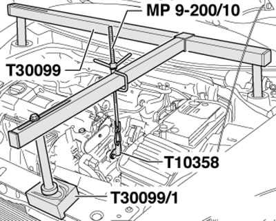
9.49. Unloading the engine mounts
Note: The illustration is based on a 1.4L engine. While rotating the spindle, slightly tighten the bracket to relieve the engine mount.
50. Press the locking buttons and disconnect the fuel supply line (3 in illustration 5.8) and a hose (4) going to the EVAP canister.
51. Remove the bolts (2 in the illustration) and pull the EVAP canister up.
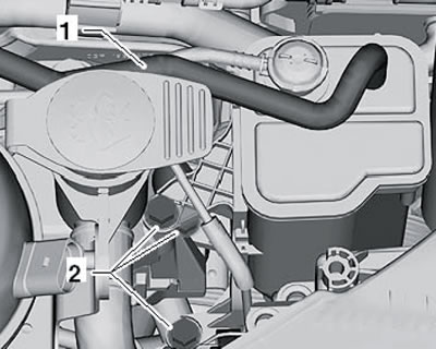
9.51. EVAP canister fastening
52. Remove the bolts (arrows in the illustration) and remove the right engine support (1).
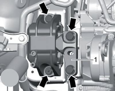
9.52. Fastening of the right engine support
53. Remove the cylinder head cover (see subsection above). When replacing a non-return valve (see illustration) tighten it to 7 Nm.
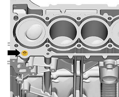
9.53. Non-return valve
54. Remove the timing chain tensioner and guide bars.
55. Remove the rocker arms together with the tappets and place them on a clean surface so that they can then be installed in their original places.
56. Remove the cylinder head mounting bolts in the following sequence: (1-10 in the illustration) and carefully remove the cylinder head.
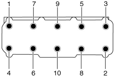
9.56. Sequence of unscrewing the cylinder head fasteners
57. Make sure that none of the pistons are in the TDC position.
58. Place a clean cloth on the cylinder block to prevent dirt or sandpaper particles from getting into the oil passages and between the pistons and cylinder walls. Carefully clean the mating surfaces of the cylinder head and block. In doing so, avoid damaging the mating surfaces. It is recommended to use a chemical remover to remove sealant and grease. When using sandpaper, its grain size should be at least 100.
59. Carefully remove metal particles, sandpaper and cloth particles. Mechanical treatment of mating surfaces is not permitted. Clean the threaded holes. Make sure there is no oil or coolant in the threaded holes of the cylinder block, otherwise the cylinder block may crack when tightening the bolts.
60. Set piston No. 1 to the TDC position, then slightly turn the crankshaft counterclockwise.
61. Place the new gasket on the cylinder block so that the part number on the gasket is legible.
Note: Do not remove the gasket from its packaging until you are ready to install the gasket; handle the gasket with care.
62. Place the cylinder head on the centering pins of the cylinder block, insert new bolts for its fastening and tighten them by hand. After this, tighten the bolts in sequence (10-1 in illustration 9.56) in several stages: first with a force of 40 Nm, and then tighten the bolts twice to an angle of 90°.
63. Install the tappets in their original places on the cylinder head and put the rocker arms on them.
64. Install the cylinder head cover (see subsection above).
65. Adjust the timing phases (see Section 10).
66. Further installation is carried out in the reverse order of removal of the remaining components.
67. Finally, fill the engine cooling system (see Chapter 3).