



Caution: The presence of metal shavings or large quantities of small metal particles found during engine rebuild may indicate damage to the crankshaft and connecting rod bearings. To prevent further damage, thoroughly clean the oil passages and replace the oil jets, oil cooler and oil filter.
Note: If the removed parts are to be reused, arrange them so that they will be in the same location and orientation when reinstalled.
1. The details of installation and assembly of the crankshaft and connecting rod-piston group are shown in the illustrations.
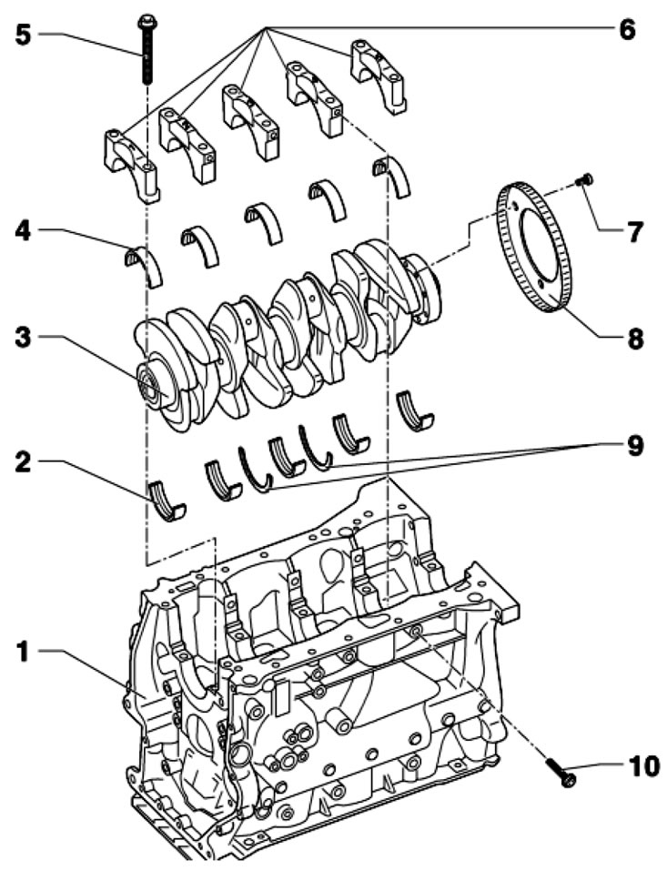
33.1a. Crankshaft installation details 1. Cylinder block; 2. Main bearings on the cylinder block side, with oil grooves; 3. Crankshaft; 4. Main bearings on the cap side, without oil grooves; 5. Bolt, subject to replacement; 6. Main bearing caps; 7. Bolt, subject to replacement, 10 Nm, then tighten to an angle of 90°, after loosening, replace the rotor 8; 8. The rotor of the CKP sensor must be replaced; 9. Main bearing thrust washers No. 3; 10. Bolt, subject to replacement
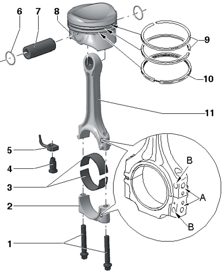
33.1b. Connecting rod and piston group installation details 1. Cover fastening bolts 2, subject to replacement, are tightened with lubricated threads and mating surface, 30 Nm, then tighten to an angle of 90°; 2. Connecting rod bearing cap, installed only in one position and only on a pair of connecting rods (see point 11); 3. Connecting rod bearing shells; 4. Pressure relief valve, 1.6+1.9 bar, 27 Nm; 5. Oil nozzle for piston cooling; 6. Retaining ring; 7. Piston pin, to facilitate removal heat the piston to 60°C; 8. Piston with combustion chamber, the arrow on the bottom should be facing the timing drive; 9. Compression rings are installed at 120° intervals between locks, the "TOP" mark should be facing the piston bottom; 10. Oil scraper ring, 2-piece, upper part lock is installed at 120° interval from the lock of the near compression ring; 11. Connecting rod, replaced only in assembly with cover 2, with mark "A" of belonging to the cylinder and mark "B" of the timing drive side
2. The numbering of the crankshaft main bearing caps starts from the timing drive side. The protrusions for holding the main bearing shells in the cylinder block and in the caps must match.
3. Main bearing shells with oil grooves are installed in the cylinder block, and without oil grooves - in the main bearing caps.
4. After removing the crankshaft, place it so that it does not rest on the CKP sensor rotor.
5. The sequence of tightening the main bearing cap bolts is shown in the illustration. First tighten the bolts (1-10) and (arrows A) by hand, then tighten the bolts (1-10) to 65 Nm, and then tighten them to an angle of 90°. Then tighten the bolts (arrows A) to 20 Nm, and then tighten them to an angle of 90°.
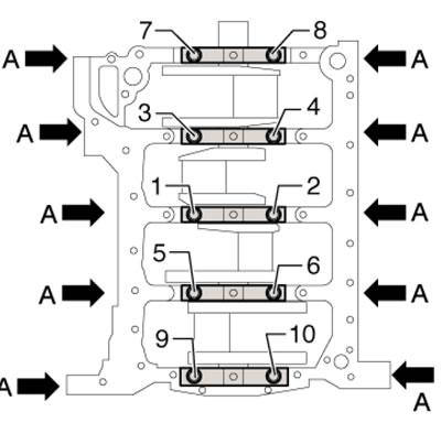
33.5. Sequence of tightening the bolts securing the main bearing caps
6. Install main bearing shells with the correct color marking, determined by the letter in the corresponding position of the code. The letter code for determining the color marking of the liners used on the cylinder block side can be indicated either on the cylinder block surface mating with the oil pan (see illustration 33.6a), or on the end of the cylinder block (see illustration 33.6b). The letter code for determining the color marking of the liners installed in the main bearing caps is indicated on the crankshaft (see illustration 33.6c). The letters in the code represent the following color markings on the inserts: S - black, R - red, B - blue, G - yellow, W - white.
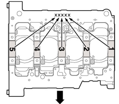
33.6a. Code for determining the marking of the upper liners (indicated on the lower surface of the cylinder block)
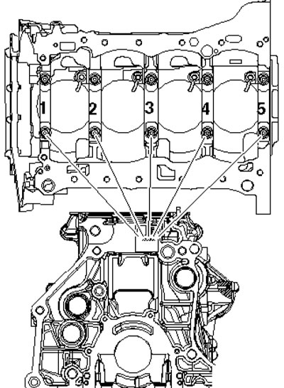
33.6b. Code for determining the marking of the upper liners (indicated on the end surface of the cylinder block)
(Material is available on the website: «skodabook»)
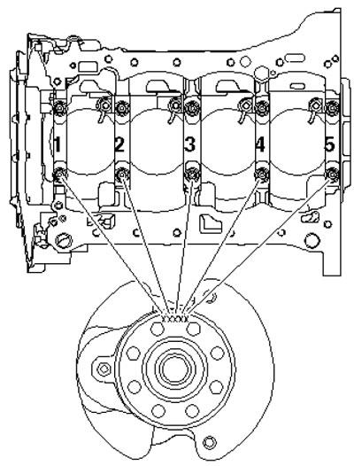
33.6c. Code for determining the marking of the lower liners
7. Connecting rods and connecting rod bearing caps are manufactured using a chipping method, so they should only be replaced together. The marks on the connecting rods and connecting rod bearing caps must be on the same side. Install connecting rod bearing shells in the center (both in the connecting rod and in its cover), to distance (and in the illustration) it was the same on both sides. Bearings with a hole are installed in the connecting rods (1), and bearings without a hole are installed in the connecting rod bearing caps (2).
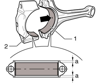
33.7. Installation position of connecting rod bearing shells
8. On new connecting rods, the connecting rod bearing cap may not be completely broken away from the connecting rod. If you can't break it off by hand, lightly secure the connecting rod in a vice with soft jaws below the break line (below the center of the hole), unscrew the cover mounting bolts by 5 turns and hit the cover with a hammer with a plastic striker (see illustration 14.4).